
Page 288 - Marine Structural Design
P. 288
264 Part II Ultimate Strength
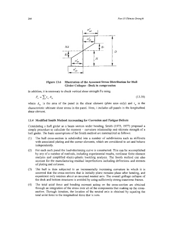
Figure 13.6 Illustration of the Assumed Stress Distribution for Hull
Girder Collapse - Deck in comprossion
In addition, it is necessary to check vertical shear strength Fu using
Fu = 1 A,, (1 3.39)
Tu,
where A,, is the area of the panel in the shear element (plate area only) and z,, is the
characteristic ultimate shear stress in the panel. Here, i includes all panels in the longitudinal
shear element.
13.4 Modified Smith Method Accounting for Corrosion and Fatigue Defects
Considering a hull girder as a beam section under bending, Smith (1975, 1977) proposed a
simple procedure to calculate the moment - curvature relationship and ultimate strength of a
hull girder. The basic assumptions of the Smith method are summarized as follows:
The hull cross-section is subdivided into a number of subdivisions such as stiffeners
with associated plating and the comer elements, which are considered to act and behave
independently.
For each such panel the load-shortening curve is constructed. This can be accomplished
by any of a number of methods, including experimental results, nonlinear finite element
analysis and simplified elastic-plastic buckling analysis. The Smith method can also
account for the manufacturing residual imperfections including deflections and stresses
of plating and columns.
The hull is then subjected to an incrementally increasing curvature in which it is
assumed that the cross-sections that is initially plane remains plane after bending, and
experience only rotation about an assumed neutral axis. The overall grillage collapse of
the deck and bottom structures is avoided by using sufficiently strong transverse frames.
The total axial force and bending moment acting on the cross-section are obtained
through an integration of the stress over all of the components that making up the cross-
section. Through iteration, the location of the neutral axis is obtained by equating the
total axial force to the longitudinal force that is zero.