
Page 361 - Marine Structural Design
P. 361
Chapter I7 Fatigue Capacity 337
, SCF
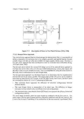
Figure 17.3 Description of Stress in Two Plated Sections (NTS, 1998)
17.2.2 Hotspot Stress Approach
The nominal stress approach has two disadvantages for tubularjoints. First, it is not possible to
define a reasonable nominal stress due to the complex geometry and applied loading. Second,
suitable fatigue test data are often not available for large complex tubularjoints. Therefore, a
hot spot stress approach has been developed in order to overcome these difficulties (Kung,
1975 and Lalani, 1992).
The hot spot stress reduces the various S-N design curves of the nominal stress approach to
two base line curves. One is the curve for non-welded structures (e.g. cutout, plate edges), and
the other is the curve for welded structures. This is accomplished by using the stress nearest to
the weld, which is defined as the hot spot fatigue stress.
The hot spot stress approach was developed based on an observation that the experimentally
derived S-N curves are nearly parallel. This implies that all the S-N curves can be related to
each other by some factors. For example, in the UK DEn Curves, the E curve, and the F curve
are correlated by a factor of 1.2 or 1.3, assuming the following:
This correlated factor represents the difference of structural configurations between
. different details.
The local fatigue failure is independent of the detail type. The difference in fatigue
resistance between details is due to different structural configurations.
The structural stress concentration factor (SCFstruct) can represent the effects of structural
configurations entirely.
The stress range at tubular joint's hot spots should be combined with the S-N curve T. The
stress range at the hot spot of plated structures should be combined with UK S-N curve D. The
C-curve may be used if machining of the weld surface to the base material is performed. Then,