
Page 362 - Marine Structural Design
P. 362
338 Part III Fatigue and Fracture
the machining has to be performed such that the local stress concentration due to the weld is
removed.
The hot spot stress concept assumes that the effect of the local stress factor, which is due to the
weld profile, should be included in the S-N curves. The stress concentration due to gross
geometry change and local geometry change should be included in the hot spot stress. The
problem with the hot spot stress approach is that the stress gradients are very high in the
vicinity of the weld and plate intersections. Because of the high gradients, the stresses
computed in FEA are extremely sensitive to the finite element mesh size. This mesh sensitivity
results in an inaccurate definition of the hot spot stress in application.
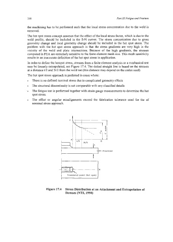
In order to define the hotspot stress, stresses ftom a finite element analysis or a mechanical test
may be linearly extrapolated, see Figure 17.4. The dotted straight line is based on the stresses
at a distance t/2 and 3t/2 from the weld toe (this distance may depend on the codes used).
The hot spot stress approach is preferred in cases where:
There is no defined nominal stress due to complicated geometry effects
The structural discontinuity is not comparable with any classified details
The fatigue test is performed together with strain gauge measurements to determine the hot
spot stress.
The offset or angular misalignments exceed the fabrication tolerance used for the of
nominal stress approach.
.
; ; '\ .
P I b
I ,
I ,
I t
A ' '
Unominal
Considered point (hot spot)
I
Figure 17.4 Stress Distribution at an Attachment and Extrapolation of
Stresses (NTS, 1998)