
Page 21 - Marks Calculation for Machine Design
P. 21
P1: Shibu
January 4, 2005
12:26
Brown.cls
Brown˙C01
CHAPTER 1
FUNDAMENTAL LOADINGS
1.1 INTRODUCTION
The fundamental loadings on machine elements are axial loading, direct shear loading,
torsion, and bending. Each of these loadings produces stresses in the machine element, as
well as deformations, meaning a change in shape. There are only two types of stresses:
normal and shear. Axial loading produces a normal stress, direct shear and torsion produce
shear stresses, and bending produces both a normal and a shear stress.
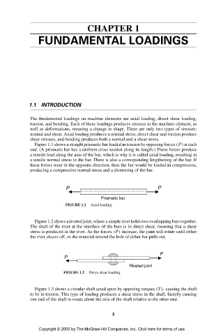
Figure 1.1 shows a straight prismatic bar loaded in tension by opposing forces (P) at each
end. (A prismatic bar has a uniform cross section along its length.) These forces produce
a tensile load along the axis of the bar, which is why it is called axial loading, resulting in
a tensile normal stress in the bar. There is also a corresponding lengthening of the bar. If
these forces were in the opposite direction, then the bar would be loaded in compression,
producing a compressive normal stress and a shortening of the bar.
P P
Prismatic bar
FIGURE 1.1 Axial loading.
Figure 1.2 shows a riveted joint, where a simple rivet holds two overlapping bars together.
The shaft of the rivet at the interface of the bars is in direct shear, meaning that a shear
stress is produced in the rivet. As the forces (P) increase, the joint will rotate until either
the rivet shears off, or the material around the hole of either bar pulls out.
P
P
Riveted joint
FIGURE 1.2 Direct shear loading.
Figure 1.3 shows a circular shaft acted upon by opposing torques (T ), causing the shaft
to be in torsion. This type of loading produces a shear stress in the shaft, thereby causing
one end of the shaft to rotate about the axis of the shaft relative to the other end.
3
Copyright © 2005 by The McGraw-Hill Companies, Inc. Click here for terms of use.