
Page 26 - Marks Calculation for Machine Design
P. 26
P1: Shibu
January 4, 2005
Brown˙C01
Brown.cls
8
U.S. Customary 12:26 STRENGTH OF MACHINES SI/Metric
Example 4. Calculate the change in diameter Example 4. Calculate the change in diameter
(
D) of a circular steel rod axially loaded in (
D) of a circular steel rod axially loaded in
compression, where compression, where
D = 2in D = 5cm
ε =−0.00025 ε =−0.00025
ν = 0.28 (steel) ν = 0.28 (steel)
solution solution
Step 1. Solve for the lateral strain from Step 1. Solve for the lateral strain from
Eq. (1.4). Eq. (1.4).
lateral strain =−ν (axial strain) lateral strain =−ν (axial strain)
Step 2. Substitute Poisson’s ratio and the axial Step 2. Substitute Poisson’s ratio and the ax-
strain (ε) that is negative because the rod is in ial strain that is negative because the rod is in
compression. compression.
lateral strain =−(0.28)(−0.00025) lateral strain =−(0.28)(−0.00025)
= 0.0007 = 0.0007
Step 3. Calculate the change in diameter (D) Step 3. Calculate the change in diameter (D)
from Eq. (1.5) using this value for the lateral from Eq. (1.5) using this value for the lateral
strain. strain.
D = D (lateral strain)
D = D (lateral strain)
= (2in)(0.0007) = (5cm)(0.0007)
= 0.0014 in = 0.0035 cm
Notice that Poisson’s ratio, the axial strain (ε), and the calculated lateral strain are the
same for both the U.S. Customary and metric systems.
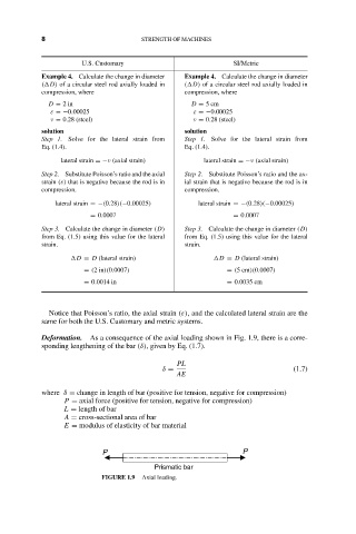
Deformation. As a consequence of the axial loading shown in Fig. 1.9, there is a corre-
sponding lengthening of the bar (δ), given by Eq. (1.7).
PL
δ = (1.7)
AE
where δ = change in length of bar (positive for tension, negative for compression)
P = axial force (positive for tension, negative for compression)
L = length of bar
A = cross-sectional area of bar
E = modulus of elasticity of bar material
P P
Prismatic bar
FIGURE 1.9 Axial loading.