Page 29 - Marks Calculation for Machine Design
P. 29

P1: Shibu
                                      12:26
                          January 4, 2005
        Brown.cls
                 Brown˙C01
                              U.S. Customary  FUNDAMENTAL LOADINGS  SI/Metric      11
                    Example 7. Calculate the change in length of  Example 7. Calculate the change in length of
                                                                          ◦
                    a steel bar that is heated to 250 F, where  a steel bar that is heated to 125 C, where
                                        ◦
                                    ◦
                                                                       ◦
                      α = 6.5 × 10 −6 in/in · F (steel)  α = 12 × 10 −6  cm/cm C (steel)
                      L = 9ft                           L = 3m
                    solution                           solution
                    Step 1. Calculate the change in length (δ T )  Step 1. Calculate the change in length (δ T )
                    owing to temperature increase using Eq. (1.10)  owing to temperature increase using Eq. (1.10).
                      δ T = α(
T ) L                    δ T = α(
T ) L
                                     ◦
                                           ◦
                        = (6.5 × 10 −6  in/in · F)(260 F)(9ft)  = (12 × 10 −6  m/m · C)(125 C)(3m)
                                                                             ◦
                                                                        ◦
                        = 0.015 ft = 0.18 in              = 0.0045 m = 0.45 cm
                    Example 8. If the bar in Example 7 is con-  Example 8. If the bar in Example 7 is con-
                    strained, then calculate the thermal stress (σ T )  strained, then calculate the thermal stress (σ T )
                    developed, where                   developed, where
                                  2
                              6
                                                                  9
                                                                      2
                      E = 30 × 10 lb/in (steel)         E = 207 × 10 N/m (steel)
                    solution                           solution
                    Step 1. Calculate the thermal strain (ε T ) using  Step 1. Calculate the thermal strain (ε T ) using
                    Eq. (1.9).                         Eq. (1.9).
                       ε T = α(
T )                       ε T = α(
T )
                                                                               ◦
                                            ◦
                                                                         ◦
                                       ◦
                          = (6.5 × 10 −6  in/in · F)(260 F)  = (12 × 10 −6  m/m · C)(125 C)
                          = 0.00169                         = 0.0015
                    Step 2. Substitute this thermal strain in  Step 2. Substitute this thermal strain in
                    Eq. (1.11) to give the thermal stress.  Eq. (1.11) to give the thermal stress.
                                                                        9
                                    6
                                                                            2
                                        2
                     σ T = Eε T = (30 × 10 lb/in )(0.00169)  σ T = Eε T = (207 × 10 N/m )(0.0015)
                                                                        2
                                 2
                        = 50,700 lb/in = 50.7 ksi          = 310,500,000 N/m = 310.5MPa
                   1.3 DIRECT SHEAR
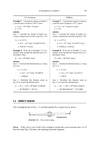
                    The overlapping bars in Fig. 1.11 are held together by a single rivet as shown.
                                                                      P
                                  P
                                                          Riveted joint
                                 FIGURE 1.11  Direct shear loading.
                    Stress.  If the rivet is cut in half at the overlap to expose the cross-sectional area (A) of
                    the rivet, then Fig. 1.12 shows the resulting free-body-diagram.
   24   25   26   27   28   29   30   31   32   33   34