
Page 34 - Marks Calculation for Machine Design
P. 34
P1: Shibu
January 4, 2005
12:26
Brown.cls
Brown˙C01
STRENGTH OF MACHINES
16
and substituting the force (F) for the shear force (V ), area (A) for a round hole from
Eq. (1.17), the ultimate shear strength (S su ) can be expressed by Eq. (1.19).
F
S su = (1.19)
2πrt
Solving for the required punching force (F) in Eq. (1.19) gives Eq. (1.20).
F = S su (2πrt) (1.20)
U.S. Customary SI/Metric
Example 3. Calculate the required punching Example 3. Calculate the required punching
force (F) for round hole, where force (F) for round hole, where
S su = 35,000 psi (aluminum) S su = 240 MPa (aluminum)
r = 0.375 in r = 1cm = 0.01 m
t = 0.25 in t = 0.65 cm = 0.0065 m
solution solution
Step 1. Calculate the required punching force Step 1. Calculate the required punching force
(F) from Eq. (1.20). (F) from Eq. (1.20).
F = S su (2πrt) F = S su (2πrt)
= (35,000 psi)(2π(0.375 in)(0.25 in)) = (240 MPa)(2π(0.01 m)(0.0065 m))
2
2
= (35,000 psi)(0.589 in ) = (240 MPa)(0.00041 m )
= 20,620 lb = 20.6 kip = 98,020 N = 98.0kN
1.4 TORSION
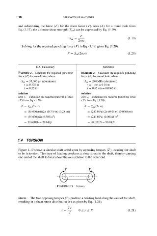
Figure 1.19 shows a circular shaft acted upon by opposing torques (T ), causing the shaft
to be in torsion. This type of loading produces a shear stress in the shaft, thereby causing
one end of the shaft to twist about the axis relative to the other end.
T T
FIGURE 1.19 Torsion.
Stress. The two opposing torques (T ) produce a twisting load along the axis of the shaft,
resulting in a shear stress distribution (τ) as given by Eq. (1.21),
Tr
τ = 0 ≤ r ≤ R (1.21)
J