Page 37 - Marks Calculation for Machine Design
P. 37

P1: Shibu
                          January 4, 2005
                                      12:26
        Brown.cls
                 Brown˙C01
                                           FUNDAMENTAL LOADINGS
                      Substituting for the respective polar moments of inertia from Eqs. (1.22) and (1.23), and
                    performing some simple algebra, gives                          19
                               1     4  4        4  4       4        4          4
                       T hollow  2  π R − R i  R − R i  R o    R i       R i
                                               o
                                    o
                             =    1        =      4     =    4    −    4    = 1 −  (1.26)
                        T solid    π R 4        R o     R o    R o       R o
                                  2   o
                      For Example 2, the ratio of the inside radius to the outside radius is one-half. So
                    Eq. (1.26) becomes
                                       4         4

                       T hollow    R i        1         1   15
                             = 1 −      = 1 −     = 1 −   =   = 0.9375 = 93.75%  (1.27)
                        T solid    R o        2        16   16
                      So what is remarkable is that removing such a large portion of the shaft only reduces
                    the torque carrying capacity by just a little over 6 percent. Note that Eq. (1.27) is a general
                    relationship and can be used for any ratio of inside and outside diameters.
                    Strain. As a consequence of the torsional loading on the circular shaft, there is a twisting
                    of the shaft along its geometric axis. This produces a shear strain (γ ) which is given in
                    Eq. (1.28), without providing the details,
                                               rφ
                                           γ =       0 ≤ r ≤ R                  (1.28)
                                                L
                    where (φ) is the angle of twist of the shaft, measured in radians.
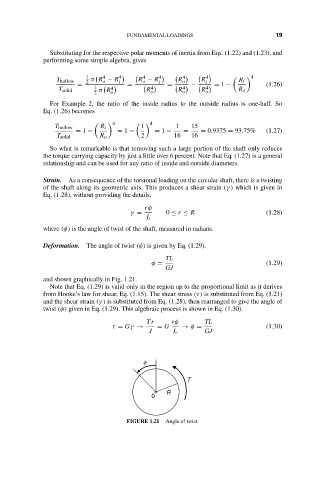
                    Deformation. The angle of twist (φ) is given by Eq. (1.29).
                                                     TL
                                                 φ =                            (1.29)
                                                     GJ
                    and shown graphically in Fig. 1.21.
                      Note that Eq. (1.29) is valid only in the region up to the proportional limit as it derives
                    from Hooke’s law for shear, Eq. (1.15). The shear stress (τ) is substituted from Eq. (1.21)
                    and the shear strain (γ ) is substituted from Eq. (1.28), then rearranged to give the angle of
                    twist (φ) given in Eq. (1.29). This algebraic process is shown in Eq. (1.30).
                                                Tr    rφ        TL
                                       τ = Gγ →    = G   → φ =                  (1.30)
                                                J      L       GJ


                                               f


                                                           T
                                                     R
                                                 0


                                          FIGURE 1.21  Angle of twist.
   32   33   34   35   36   37   38   39   40   41   42