
Page 40 - Marks Calculation for Machine Design
P. 40
P1: Shibu
12:26
January 4, 2005
Brown˙C01
Brown.cls
STRENGTH OF MACHINES
22
Thin-walled Tubes. For either a solid or hollow circular shaft, Eq. (1.21) gives the shear
stress (τ) because of torsion. For thin-walled tubes of any shape Eq. (1.31) gives the shear
stress (τ) in the wall of the tube owing to an applied torque (T ).
T
τ = (1.31)
2 A m t
where A m is area enclosed by the median line of the tube cross section and t is thickness
of the tube wall.
Suprisingly, the angle of twist (φ) for thin-walled tubes is the same as presented in
Eq. (1.29), that is
TL
φ = (1.32)
GJ
However, each thin-walled tube shape will have a different polar moment of
inertia (J).
Equations (1.31) and (1.32) are useful for all kinds of thin-walled shapes: elliptical,
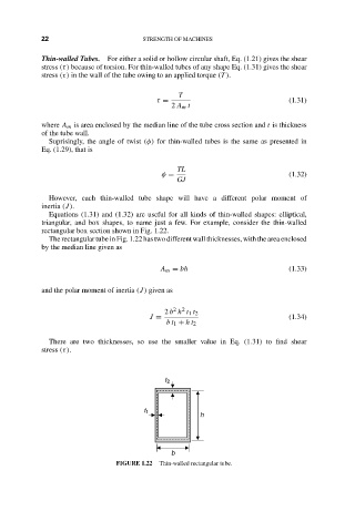
triangular, and box shapes, to name just a few. For example, consider the thin-walled
rectangular box section shown in Fig. 1.22.
The rectangular tube in Fig. 1.22 has two different wall thicknesses, with the area enclosed
by the median line given as
A m = bh (1.33)
and the polar moment of inertia (J) given as
2 2
2 b h t 1 t 2
J = (1.34)
bt 1 + ht 2
There are two thicknesses, so use the smaller value in Eq. (1.31) to find shear
stress (τ).
t 2
t 1
h
b
FIGURE 1.22 Thin-walled rectangular tube.