
Page 42 - Marks Calculation for Machine Design
P. 42
P1: Shibu
January 4, 2005
12:26
Brown˙C01
Brown.cls
24
STRENGTH OF MACHINES
BENDING
1.5
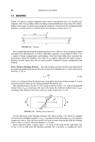
Figure 1.23 shows a simply-supported beam with a concentrated force (F) located at its
midpoint. This force produces both a bending moment distribution and a shear force distri-
bution in the beam. At any location along the length (L) of the beam, the bending moment
produces a normal stress (σ) and the shear force produces a shear stress (τ).
F
L/2
A B
L
FIGURE 1.23 Bending.
It is assumed that the bending moment and shear force is known. If not, bending moment
and shear force distributions, as well as deflection equations, are provided in Chap. 2 for
a variety of beam configurations and loadings. Note that beam deflections represent the
deformation caused by bending. Also, there is no explicit expression for strain owing to
bending, because again, there are so many possible variations in beam configuration and
loading.
Stress Owing to Bending Moment. Once the bending moment (M) has been determined
at a particular point along a beam, then the normal stress distribution (σ) can be determined
from Eq. (1.35) as
My
σ = (1.35)
I
where (y) is distance from the neutral axis (centroid) to the point of interest and (I) is area
moment of inertia about an axis passing through the neutral axis.
The distribution given by Eq. (1.35) is linear as shown in Fig. 1.24, with the maximum
normal stress (σ max ) occurring at the top of the beam, the minimum normal stress (σ min )
occurring at the bottom of the beam, and zero at the neutral axis (y = 0).
s max
y
M 0 M
s min
FIGURE 1.24 Bending stress distribution.
For the directions of the bending moments (M) shown in Fig. 1.24, which by standard
convention are considered negative, (σ max ) is a positive tensile stress and (σ min ) is a negative
compressive stress. Also, the term neutral axis gets its name from the fact that the bending
stress is zero, or neutral, when the distance (y) is zero.
Some references place a minus sign (−) in front of the term on the right hand side
of Eq. (1.35) so that when the bending moment (M) is positive, a compressive stress