
Page 45 - Marks Calculation for Machine Design
P. 45
P1: Shibu
January 4, 2005
12:26
Brown˙C01
Brown.cls
FUNDAMENTAL LOADINGS
27
Shear Stress Owing to Bending. Once the shear force (V ) has been determined at a partic-
ular point along a beam, the shear stress distribution (τ) can be determined from Eq. (1.39) as
VQ
τ = (1.39)
Ib
where Q = Ay, first moment of area (A)
A = area out beyond point of interest, specified by distance (y)
y = distance to centroid of area (A) defined above
I = area moment of inertia about an axis passing through neutral axis
b = width of beam at point of interest
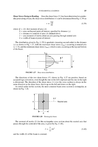
The distribution given by Eq. (1.39) is quadratic (meaning second order) in the distance
(y) as shown in Fig. 1.27, with the maximum shear stress (τ max ) occurring at neutral axis
(y = 0), and the minimum shear stress (τ min ), which is zero, occurring at the top and bottom
of the beam.
t min
y
V 0 V
t max
t min
FIGURE 1.27 Shear stress distribution.
The directions of the two shear forces (V ) shown in Fig. 1.27 are positive, based on
accepted sign convention, even though the one on the left is upward and the one on the right
is downward. The direction of the shear stress (τ) over the cross section is always in the
same direction as the shear force, that is up on the left and down on the right.
As stated earlier in this section, the most common beam cross section is rectangular, as
shown in Fig. 1.28.
y
h Neutral axis
b
FIGURE 1.28 Rectangular beam.
The moment of inertia (I) for this rectangular cross section about the neutral axis that
passes through the centroid of the area, is given by Eq. (1.40),
1 3
I = bh (1.40)
12
and the width (b) of the beam is constant.