Page 49 - Marks Calculation for Machine Design
P. 49

P1: Shibu
                          January 4, 2005
                                      12:26
        Brown.cls
                 Brown˙C01
                                           FUNDAMENTAL LOADINGS
                                                                                   31
                      From equilibrium, the two shear forces (V ) are equal to the applied force (2P),soa
                    single shear force (V ) equals a single applied force (P) and the shear stress (τ) is given by
                    Eq. (1.44) as
                                                  V    P
                                              τ =   =                           (1.44)
                                                  A   A rivet
                      [Note that the applied force (P) in Eq. (1.44) is twice the applied force (P) in Eq. (1.43).]
                      Consider a modification of the overlapping joint in Fig. 1.33, where now there are gaps
                    between the plates as shown in Fig. 1.35, and the rivet is no longer under direct shear
                    loading but shear owing to bending. This means the rivet is acting like a beam and so the
                    shear stress (τ) is given by Eq. (1.45).
                                                     VQ
                                                 τ =                            (1.45)
                                                     Ib
                                P
                                                                      2P
                                                           Gaps
                                P
                                FIGURE 1.35  Shear owing to bending.


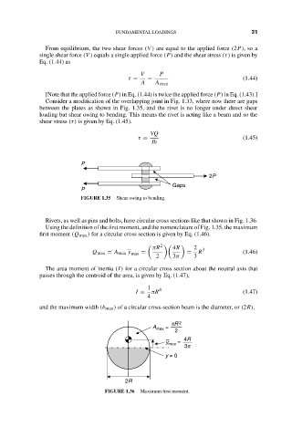
                      Rivets, as well as pins and bolts, have circular cross sections like that shown in Fig. 1.36.
                      Using the definition of the first moment, and the nomenclature of Fig. 1.35, the maximum
                    first moment (Q max ) for a circular cross section is given by Eq. (1.46).

                                                        2
                                                     πR    4R     2  3
                                    Q max = A max y max  =     =   R            (1.46)
                                                      2    3π     3
                      The area moment of inertia (I) for a circular cross section about the neutral axis that
                    passes through the centroid of the area, is given by Eq. (1.47),
                                                    1  4
                                                I =  πR                         (1.47)
                                                    4
                    and the maximum width (b max ) of a circular cross-section beam is the diameter, or (2R).

                                                           pR 2
                                                     A max  =
                                                            2
                                                               4R
                                                         y max  =
                                                               3p
                                                         y = 0


                                             2R
                                       FIGURE 1.36  Maximum first moment.
   44   45   46   47   48   49   50   51   52   53   54