
Page 54 - Marks Calculation for Machine Design
P. 54
P1: Sanjay
January 4, 2005
16:18
Brown.cls
Brown˙C02
36
STRENGTH OF MACHINES
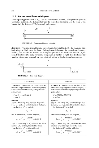
2.2.1 Concentrated Force at Midpoint
The simply-supported beam in Fig. 2.9 has a concentrated force (F) acting vertically down-
ward at its midpoint. The distance between the supports is labeled (L), so the force (F) is
located half the distance (L/2) from each end support.
L/2 F
A B
L
FIGURE 2.9 Concentrated force at midpoint.
Reactions. The reactions at the end supports are shown in Fig. 2.10—the balanced free-
body-diagram. Notice that the force (F) is split evenly between the vertical reactions (A y
and B y ), and because the force (F) is acting straight down, the horizontal reaction (A x ) is
zero. If the force (F) had a horizontal component, either left or right, then the horizontal
reaction (A x ) would be equal, but opposite in direction, to this horizontal component.
F
A = 0
x
A = F/2 B = F/2
y
y
FIGURE 2.10 Free-body-diagram.
U.S. Customary SI/Metric
Example 1. Determine the reactions at the Example 1. Determine the reactions at the
ends of a simply-supported beam of length (L) ends of a simply-supported beam of length (L)
with a concentrated force (F) acting at its mid- with a concentrated force (F) acting at its mid-
point, where point, where
F = 12 kip = 12,000 lb F = 55 kN = 55,000 N
L = 6ft L = 2m
solution solution
Step 1. From Fig. 2.10, calculate the pin reac- Step 1. From Fig. 2.10 calculate the pin reac-
tions (A x and A y ) at the left end of the beam. tions (A x and A y ) at the left end of the beam.
As the force (F) is vertical, As the force (F) is vertical,
A x = 0 A x = 0
and as the force (F) is at the midpoint, and as the force (F) is at the midpoint,
F 12,000 lb F 55,000 N
A y = = = 6,000 lb A y = = = 27,500 N
2 2 2 2
Step 2. From Fig. 2.10, calculate the roller Step 2. From Fig. 2.10, calculate the roller
reaction (B y ) at the right end of the beam. reaction (B y ) at the right end of the beam.
As the force (F) is at the midpoint, As the force (F) is at the midpoint,
F 12,000 lb F 55,000 N
B y = = = 6,000 lb B y = = = 27,500 N
2 2 2 2