
Page 57 - Marks Calculation for Machine Design
P. 57
P1: Sanjay
January 4, 2005
16:18
Brown.cls
Brown˙C02
U.S. Customary BEAMS SI/Metric 39
solution solution
Step 1. Calculate the maximum shear force Step 1. Calculate the maximum shear force
(V max ) from Eq. (2.1) as (V max ) from Eq. (2.1) as
F 12,000 lb F 55,000 N
V max = = = 6,000 lb V max = = = 27,500 N
2 2 2 2
Step 2. As shown in Fig. 2.13, this maximum Step 2. As shown in Fig. 2.13, this maximum
shear force (V max ) of 6,000 lb does not have a shear force (V max ) of 27,500 N does not have a
specific location. specific location.
Step 3. Calculate the maximum bending Step 3. Calculate the maximum bending
moment (M max ) from Eq. (2.3) as moment (M max ) from Eq. (2.3) as
FL (12,000 lb)(6ft) FL (55,000 N)(2m)
M max = = M max = =
4 4 4 4
72,000 ft · lb 110,000 N · m
= = 18,000 ft · lb = = 27,500 N · m
4 4
Step 4. Figure 2.14 shows that this maximum Step 4. As shown in Fig. 2.14, this maximum
bending moment (M max ) of 18,000 ft · lb is bending moment (M max ) of 27,500 N · mis
located at the midpoint of the beam. located at the midpoint of the beam.
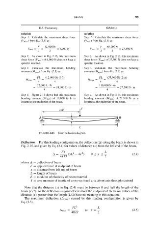
L/2 F
A ∆ B
L
FIGURE 2.15 Beam deflection diagram.
Deflection. For this loading configuration, the deflection ( ) along the beam is shown in
Fig. 2.15, and given by Eq. (2.4) for values of distance (x) from the left end of the beam,
Fx 2 2 L
= (3L − 4x ) 0 ≤ x ≤ (2.4)
48 EI 2
where = deflection of beam
F = applied force at midpoint of beam
x = distance from left end of beam
L = length of beam
E = modulus of elasticity of beam material
I = area moment of inertia of cross-sectional area about axis through centroid
Note that the distance (x) in Eq. (2.4) must be between 0 and half the length of the
beam (L/2). As the deflection is symmetrical about the midpoint of the beam, values of the
distance (x) greater than the length (L/2) have no meaning in this equation.
The maximum deflection ( max ) caused by this loading configuration is given by
Eq. (2.5),
FL 3 L
max = at x = (2.5)
48 EI 2