Page 59 - Marks Calculation for Machine Design
P. 59

P1: Sanjay
                                      16:18
                          January 4, 2005
        Brown.cls
                 Brown˙C02
                              U.S. Customary     BEAMS            SI/Metric        41
                    solution                           solution
                    Step 1. Calculate the maximum deflection  Step 1. Calculate the maximum deflection
                    from Eq. (2.5).                    from Eq. (2.5).
                              FL 3                             FL 3
                         max =                            max =
                             48 (EI)                          48 (EI)
                              (12,000 lb)(6ft) 3               (55,000 N)(2m) 3
                           =                                =
                                                                           2
                                                                       5
                                          2
                                      5
                             48 (4.69 × 10 lb · ft )          48 (1.82 × 10 N · m )
                                                                    5
                                   6
                             2.59 × 10 lb · ft 3              4.40 × 10 N · m 3
                           =                                =       6    2
                                   7
                             2.25 × 10 lb · ft 2              8.74 × 10 N · m
                                    12 in                             100 cm
                           = 0.115 ft ×  = 1.38 in ↓        = 0.0504 m ×   = 5.04 cm ↓
                                     ft                                m
                      Notice that the maximum deflection (  max ) found at the midpoint of the beam (L/2) in
                    Example 5 is not twice the deflection ( ) at a distance one quarter the length of the beam
                    (L/4) found in Example 4. This is because the shape of the deflection curve is parabolic,
                    not linear.
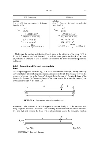
                    2.2.2 Concentrated Force at Intermediate
                    Point
                    The simply-supported beam in Fig. 2.16 has a concentrated force (F) acting vertically
                    downward at an intermediate point, meaning not at its midpoint. The distance between the
                    supports is labeled (L), so the force (F) is located at a distance (a) from the left end of the
                    beam and a distance (b) from the right end of the beam, where the sum of distances (a) and
                    (b) equal the length of the beam (L).
                                                               F
                                               a                    b

                              A                                           B
                                                    L
                              FIGURE 2.16  Concentrated force at intermediate point.

                    Reactions.  The reactions at the end supports are shown in Fig. 2.17, the balanced free-
                    body-diagram. Notice that the force (F) is unevenly divided between the vertical reactions
                    (A y and B y ), and because the force (F) is acting straight down, the horizontal reaction


                                                              F
                                             a                    b
                         A  = 0
                          x

                               A  = Fb/L                                 B  = Fa/L
                                y
                                                                          y
                        FIGURE 2.17  Free-body-diagram.
   54   55   56   57   58   59   60   61   62   63   64