
Page 56 - Marks Calculation for Machine Design
P. 56
P1: Sanjay
January 4, 2005
Brown˙C02
Brown.cls
38
M
FL/4 16:18 STRENGTH OF MACHINES
+ +
0 x
L/2 L
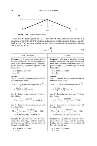
FIGURE 2.14 Bending moment diagram.
Note that the bending moment (M) is zero at both ends, and increases linearly to a
maximum at the midpoint (L/2). From the midpoint, the bending moment decreases linearly
back to zero. The maximum bending moment (M max ) occurs at the midpoint of the beam
and is given by Eq. (2.3).
FL
M max = (2.3)
4
U.S. Customary SI/Metric
Example 2. Calculate the shear force (V ) and Example 2. Calculate the shear force (V ) and
bending moment (M) for a simply-supported bending moment (M) for a simply-supported
beam with a concentrated force (F) at its mid- beam with a concentrated force (F) at its mid-
point a distance (L/4) from the right end of the point a distance (L/4) from the right end of the
beam, where beam, where
F = 12 kip = 12,000 lb F = 55 kN = 55,000 N
L = 6ft L = 2m
solution solution
Step 1. Establish the distance (x) from the left Step 1. Establish the distance (x) from the left
end of the beam, where end of the beam, where
L 3L L 3L
x = L − (distance from right end) = x = L − (distance from right end) =
4 4 4 4
3 (6ft) 18 ft 3 (2m) 6m
= = = 4.5ft = = = 1.5m
4 4 4 4
Step 2. Determine the shear force (V ) from Step 2. Determine the shear force (V ) from
Fig. 2.13 as Fig. 2.13 as
F 12,000 lb F 55,000 N
V =− =− =−6,000 lb V =− =− =−27,500 N
2 2 2 2
Step 3. Determine the bending moment (M) Step 3. Determine the bending moment (M)
from Eq. (2.2b). from Eq. (2.2b).
F 12,000 lb F 55,000 N
M = (L − x) = (6ft − 4.5ft) M = (L − x) = (2m − 1.5m)
2 2 2 2
= (6,000 lb)(1.5ft) = 9,000 ft · lb = (27,500 N)(0.5m) = 13,750 N · m
Example 3. Calculate and locate the max- Example 3. Calculate and locate the max-
imum shear force (V max ) and the maximum imum shear force (V max ) and the maximum
bending moment (M max ) for the beam of bending moment (M max ) for the beam of
Examples 1 and 2, where Examples 1 and 2, where
F = 12 kip = 12,000 lb F = 55 kN = 55,000 N
L = 6ft L = 2m