
Page 51 - Marks Calculation for Machine Design
P. 51
P1: Sanjay
16:18
January 4, 2005
Brown.cls
Brown˙C02
CHAPTER 2
BEAMS: REACTIONS, SHEAR
FORCE AND BENDING
MOMENT DISTRIBUTIONS,
AND DEFLECTIONS
2.1 INTRODUCTION
Virtually all machines, especially complex ones, have one or more elements acting as
beams. Unlike axial loading that is either tensile or compressive, or torsional loading that
is either clockwise or counterclockwise, there is what appears to be an infinite number of
possible loadings associated with beams. The number is obviously not infinite; but with
the possible types of loads that a beam can support (e.g., forces, couples, or distributed
loads), the possible types of beam supports (pin, roller, or cantilever), and the possible
combinations of these loads and supports, the number of unique beam configurations can
easily seem infinite.
The beam and loading configurations presented in this book cover the important ones
that mechanical engineers are likely to encounter. These configurations are divided into
two main categories: simply-supported and cantilevered, with simply-supported category
divided into three subcategories. In all, there are 15 beam and loading configurations. For
each beam configuration, there are, on average, five example calculations presented to
include finding support reactions, shear force and bending moments, and deflections. This
means there are over 75 such examples provided.
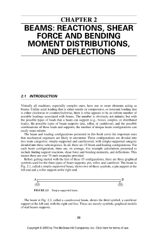
Before getting started with the first of these 15 configurations, there are three graphical
symbols used for the three types of beam supports: pin, roller, and cantilever. The beam in
Fig. 2.1, called a simply-supported beam, shows two of these symbols, a pin support at the
left end and a roller support at the right end.
A B
FIGURE 2.1 Simply-supported beam.
The beam in Fig. 2.2, called a cantilevered beam, shows the third symbol, a cantilever
support at the left end, with the right end free. These are merely symbols; graphical models
of real beams supports.
33
Copyright © 2005 by The McGraw-Hill Companies, Inc. Click here for terms of use.