
Page 53 - Marks Calculation for Machine Design
P. 53
P1: Sanjay
January 4, 2005
Brown˙C02
Brown.cls
A 16:18 A BEAMS A x 35
A y C A
(a) (b) (c)
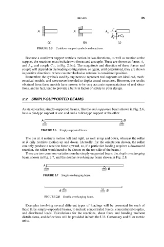
FIGURE 2.5 Cantilever support symbols and reactions.
Because a cantilever support restricts motion in two directions, as well as rotation at the
support, the reactions must include two forces and a couple. These are shown as forces A x
and A y , and couple C A , in Fig. 2.5(c). The magnitude and direction of these forces and
couple will depend on the loading configuration, so again, until determined, they are shown
in positive directions, where counterclockwise rotation is considered positive.
Remember, the symbols used by engineers to represent real supports are idealized, math-
ematical models, and were never intended to depict actual structures. However, the results
obtained from these models have proven to be very accurate representations of real situa-
tions, and in fact, tend to provide a built-in factor of safety to your design.
2.2 SIMPLY-SUPPORTED BEAMS
As stated earlier, simply-supported beams, like the end-supported beam shown in Fig. 2.6,
have a pin-type support at one end and a roller-type support at the other.
A B
FIGURE 2.6 Simply-supported beam.
The pin at A restricts motion left and right, as well as up and down, whereas the roller
at B only restricts motion up and down. (Actually, for the orientation shown, the roller
can only produce a reaction force upward, so, if a particular loading requires a downward
reaction, the roller would need to be shown on the top side of the beam.)
There are two common variations on the simply-supported beam: the single overhanging
beam shown in Fig. 2.7, and the double overhanging beam shown in Fig. 2.8.
A
B
FIGURE 2.7 Single overhanging beam.
A B
FIGURE 2.8 Double overhanging beam.
Examples involving several different types of loadings will be presented for each of
these three simply-supported beams, to include concentrated forces, concentrated couples,
and distributed loads. Calculations for the reactions, shear force and bending moment
distributions, and deflections will be provided in both the U.S. Customary and SI or metric
units.