
Page 52 - Marks Calculation for Machine Design
P. 52
P1: Sanjay
January 4, 2005
Brown˙C02
Brown.cls
34
A 16:18 STRENGTH OF MACHINES B
FIGURE 2.2 Cantilevered beam.
The first idealized symbol, the pin support shown at point A in Fig. 2.3(a), looks like a
knife edge, but it is not. It represents the ability of this type of support to restrict motion
left and right, as well as up and down. The graphical symbol shown in Fig. 2.3(b) shows
why this is called a pin support, in that for a real support of this type there is physically a
pin connecting the beam to some type of clevis structure attached to the foundation. For the
beams that will be presented, this level of detail is unnecessary. Foundations, depicted by a
straight line and hash marks, are always assumed to be rigid.
A A A x
A y
(a) (b) (c)
FIGURE 2.3 Pin support symbols and reactions.
Whenever there is a restriction in motion, there must be a force present to cause this
restriction. As a pin support restricts motion in two directions, there must be two forces
present, called reaction forces, shown as A x and A y in Fig. 2.3(c). The magnitude and
direction of these two forces will depend on the loading configuration, so until they are
determined, these forces are usually shown in positive directions.
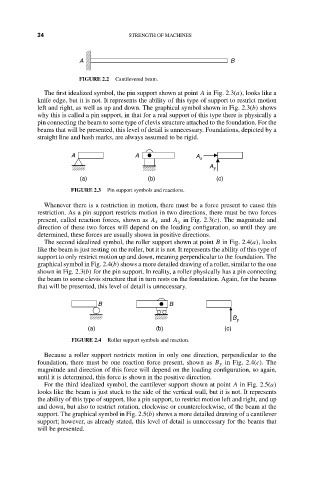
The second idealized symbol, the roller support shown at point B in Fig. 2.4(a), looks
like the beam is just resting on the roller, but it is not. It represents the ability of this type of
support to only restrict motion up and down, meaning perpendicular to the foundation. The
graphical symbol in Fig. 2.4(b) shows a more detailed drawing of a roller, similar to the one
shown in Fig. 2.3(b) for the pin support. In reality, a roller physically has a pin connecting
the beam to some clevis structure that in turn rests on the foundation. Again, for the beams
that will be presented, this level of detail is unnecessary.
B B
B
y
(a) (b) (c)
FIGURE 2.4 Roller support symbols and reaction.
Because a roller support restricts motion in only one direction, perpendicular to the
foundation, there must be one reaction force present, shown as B y in Fig. 2.4(c). The
magnitude and direction of this force will depend on the loading configuration, so again,
until it is determined, this force is shown in the positive direction.
For the third idealized symbol, the cantilever support shown at point A in Fig. 2.5(a)
looks like the beam is just stuck to the side of the vertical wall, but it is not. It represents
the ability of this type of support, like a pin support, to restrict motion left and right, and up
and down, but also to restrict rotation, clockwise or counterclockwise, of the beam at the
support. The graphical symbol in Fig. 2.5(b) shows a more detailed drawing of a cantilever
support; however, as already stated, this level of detail is unnecessary for the beams that
will be presented.