
Page 55 - Marks Calculation for Machine Design
P. 55
P1: Sanjay
January 4, 2005
Brown˙C02
Brown.cls
F
A 16:18 L/2 BEAMS B 37
L
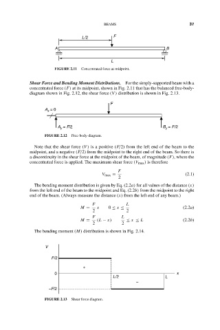
FIGURE 2.11 Concentrated force at midpoint.
Shear Force and Bending Moment Distributions. For the simply-supported beam with a
concentrated force (F) at its midpoint, shown in Fig. 2.11 that has the balanced free-body-
diagram shown in Fig. 2.12, the shear force (V ) distribution is shown in Fig. 2.13.
F
A = 0
x
A = F/2 B = F/2
y
y
FIGURE 2.12 Free-body-diagram.
Note that the shear force (V ) is a positive (F/2) from the left end of the beam to the
midpoint, and a negative (F/2) from the midpoint to the right end of the beam. So there is
a discontinuity in the shear force at the midpoint of the beam, of magnitude (F), where the
concentrated force is applied. The maximum shear force (V max ) is therefore
F
V max = (2.1)
2
The bending moment distribution is given by Eq. (2.2a) for all values of the distance (x)
from the left end of the beam to the midpoint and Eq. (2.2b) from the midpoint to the right
end of the beam. (Always measure the distance (x) from the left end of any beam.)
F L
M = x 0 ≤ x ≤ (2.2a)
2 2
F L
M = (L − x) ≤ x ≤ L (2.2b)
2 2
The bending moment (M) distribution is shown in Fig. 2.14.
V
F/2
+
0 x
L/2 L
–
–F/2
FIGURE 2.13 Shear force diagram.