
Page 60 - Marks Calculation for Machine Design
P. 60
P1: Sanjay
16:18
January 4, 2005
Brown.cls
Brown˙C02
STRENGTH OF MACHINES
42
(A x ) is zero. If the force (F) had a horizontal component, then the horizontal reaction (A x )
would be equal, but opposite in direction, to this horizontal component.
U.S. Customary SI/Metric
Example 1. Determine the reactions at the Example 1. Determine the reactions at the
ends of a simply-supported beam of length (L) ends of a simply-supported beam of length (L)
with a concentrated force (F) acting at an inter- with a concentrated force (F) acting at an inter-
mediate point, where mediate point, where
F = 10 kip = 10,000 lb F = 45 kN = 45,000 N
L = 8 ft, a = 6 ft, b = 2ft L = 3m, a = 2m, b = 1m
solution solution
Step 1. From Fig. 2.17, calculate the pin reac- Step 1. From Fig. 2.17, calculate the pin reac-
tions (A x and A y ) at the left end of the beam. tions (A x and A y ) at the left end of the beam.
As the force (F) is vertical, As the force (F) is vertical,
A x = 0 A x = 0
and the vertical reaction (A y ) is and the vertical reaction (A y ) is
Fb (10,000 lb)(2ft) Fb (45,000 N)(1m)
A y = = A y = =
L 8ft L 3m
20,000 ft · lb 45,000 N · m
= = 2,500 lb = = 15,000 N
8ft 3m
Step 2. From Fig. 2.17 calculate the roller re- Step 2. From Fig. 2.17 calculate the roller re-
action (B y ) at the right end of the beam. action (B y ) at the right end of the beam.
Fa (10,000 lb)(6ft) Fa (45,000 N)(2m)
B y = = B y = = ·
L 8ft L 3m
60,000 ft · lb 90,000 N · m
= = 7,500 lb = = 30,000 N
8ft 3m
F
a b
A B
L
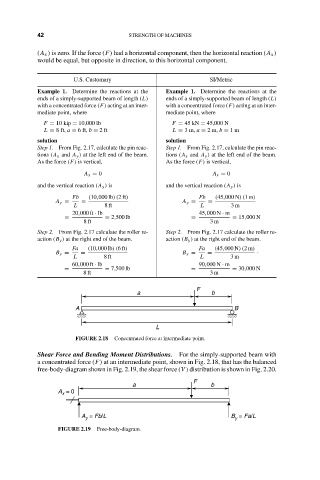
FIGURE 2.18 Concentrated force at intermediate point.
Shear Force and Bending Moment Distributions. For the simply-supported beam with
a concentrated force (F) at an intermediate point, shown in Fig. 2.18, that has the balanced
free-body-diagram shown in Fig. 2.19, the shear force (V ) distribution is shown in Fig. 2.20.
F
a b
A = 0
x
A = Fb/L B = Fa/L
y
y
FIGURE 2.19 Free-body-diagram.