
Page 63 - Marks Calculation for Machine Design
P. 63
P1: Sanjay
16:18
January 4, 2005
Brown.cls
Brown˙C02
U.S. Customary BEAMS SI/Metric 45
Step 3. Calculate the maximum bending Step 3. Calculate the maximum bending
moment (M max ) from Eq. (2.8) as moment (M max ) from Eq. (2.8) as
Fab (10,000 1b)(6ft)(2ft) Fab (45,000 N)(2m)(1m)
M max = = M max = =
L 8ft L 3m
2
120,000 ft · lb 90,000 N · m 2
= = 15,000 ft · lb = = 30,000 N · m
8ft 3m
Step 4. Figure 2.21, this maximum bending Step 4. Figure 2.21, this maximum bending
moment (M max ) of 15,000 ft · lb occurs where moment (M max ) of 30,000 N · m occurs where
the force (F) acts. the force (F) acts.
F
a b
A ∆ B
L
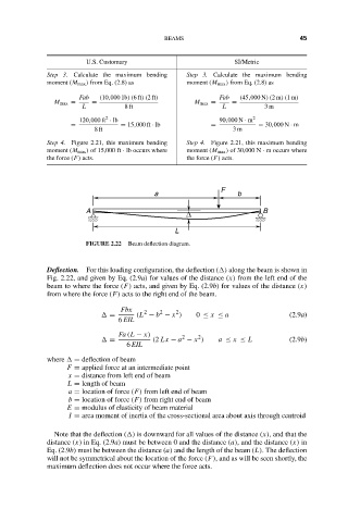
FIGURE 2.22 Beam deflection diagram.
Deflection. For this loading configuration, the deflection ( ) along the beam is shown in
Fig. 2.22, and given by Eq. (2.9a) for values of the distance (x) from the left end of the
beam to where the force (F) acts, and given by Eq. (2.9b) for values of the distance (x)
from where the force (F) acts to the right end of the beam.
Fbx 2 2 2
= (L − b − x ) 0 ≤ x ≤ a (2.9a)
6 EIL
Fa (L − x) 2 2
= (2 Lx − a − x ) a ≤ x ≤ L (2.9b)
6 EIL
where = deflection of beam
F = applied force at an intermediate point
x = distance from left end of beam
L = length of beam
a = location of force (F) from left end of beam
b = location of force (F) from right end of beam
E = modulus of elasticity of beam material
I = area moment of inertia of the cross-sectional area about axis through centroid
Note that the deflection ( ) is downward for all values of the distance (x), and that the
distance (x) in Eq. (2.9a) must be between 0 and the distance (a), and the distance (x) in
Eq. (2.9b) must be between the distance (a) and the length of the beam (L). The deflection
will not be symmetrical about the location of the force (F), and as will be seen shortly, the
maximum deflection does not occur where the force acts.