Page 67 - Marks Calculation for Machine Design
P. 67

P1: Sanjay
                          January 4, 2005
                                      16:18
        Brown.cls
                 Brown˙C02
                                  a
                                                                       x
                                       C         BEAMS b              B  = 0       49
                            A  = C/L                                  B  = −C/L
                             y
                                                                       y
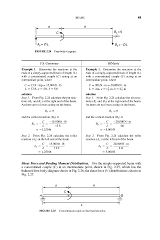
                           FIGURE 2.24  Free-body-diagram.
                              U.S. Customary                      SI/Metric
                    Example 1. Determine the reactions at the  Example 1. Determine the reactions at the
                    ends of a simply-supported beam of length (L)  ends of a simply-supported beam of length (L)
                    with a concentrated couple (C) acting at an  with a concentrated couple (C) acting at an
                    intermediate point, where          intermediate point, where
                     C = 15 ft · kip = 15,000 ft · lb   C = 20 kN · m = 20,000 N · m
                                                                          1
                                                                   1
                      L = 12 ft, a = 4 ft, b = 8ft      L = 4m, a = 1 m, b = 2 m
                                                                   2      2
                    solution                           solution
                    Step 1. From Fig. 2.24 calculate the pin reac-  Step 1. From Fig. 2.24 calculate the pin reac-
                    tions (B x and B y ) at the right end of the beam.  tions (B x and B y ) at the right end of the beam.
                    As there are no forces acting on the beam,  As there are no forces acting on the beam,
                                 B x = 0                           B x = 0
                    and the vertical reaction (B y ) is  and the vertical reaction (B y ) is
                               C   −15,000 ft · lb                C  −20,000 N · m
                         B y =−  =                          B y =−  =
                               L      12 ft                       L      4m
                            =−1,250 lb                        =−5,000 N
                    Step 2. From Fig. 2.24 calculate the roller  Step 2. From Fig. 2.24 calculate the roller
                    reaction (A y ) at the left end of the beam.  reaction (A y ) at the left end of the beam.
                               C   15,000 ft · lb                 C  20,000 N · m
                           A y =  =                          A y =  =
                               L     12 ft                        L     4m
                             = 1,250 lb                         = 5,000 N

                    Shear Force and Bending Moment Distributions.  For the simply-supported beam with
                    a concentrated couple (C) at an intermediate point, shown in Fig. 2.25, which has the
                    balanced free-body-diagram shown in Fig. 2.26, the shear force (V ) distribution is shown in
                    Fig. 2.27.


                                      a                    b
                                           C
                              A                                           B

                                                    L
                              FIGURE 2.25  Concentrated couple at intermediate point.
   62   63   64   65   66   67   68   69   70   71   72