Page 68 - Marks Calculation for Machine Design
P. 68

P1: Sanjay
                                      16:18
                          January 4, 2005
        Brown.cls
                 Brown˙C02
                                           STRENGTH OF MACHINES
                  50
                                 a
                                                     b
                                                                    B  = 0
                                     C                               x
                           A  = C/L                                  B  = –C/L
                            y
                                                                      y
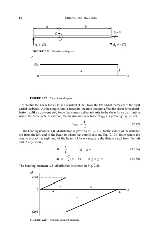
                          FIGURE 2.26  Free-body-diagram.
                         V
                           C/L
                                                   +                    L
                            0                                               x


                        FIGURE 2.27  Shear force diagram.
                    Note that the shear force (V ) is a constant (C/L) from the left end of the beam to the right
                  end of the beam. As the couple is not a force, its location does not affect the shear force distri-
                  bution, unlike a concentrated force that causes a discontinuity in the shear force distribution
                  where the force acts. Therefore, the maximum shear force (V max ) is given by Eq. (2.12).
                                                     C
                                               V max =                         (2.12)
                                                     L
                    The bending moment (M) distribution is given by Eq. (2.13a) for the values of the distance
                  (x) from the left end of the beam to where the couple acts and Eq. (2.13b) from where the
                  couple acts to the right end of the beam. (Always measure the distance (x) from the left
                  end of any beam.)
                                           C
                                      M =    x   0 ≤ x ≤ a                    (2.13a)
                                           L
                                            C
                                      M =−    (L − x)  a ≤ x ≤ L              (2.13b)
                                            L
                  The bending moment (M) distribution is shown in Fig. 2.28.

                        M
                         Ca/L

                                        +               b
                            0                                               x
                                    a                                   L
                                                 −


                        −Cb/L

                        FIGURE 2.28  Bending moment diagram.
   63   64   65   66   67   68   69   70   71   72   73