Page 48 - Marks Calculation for Machine Design
P. 48

P1: Shibu
                          January 4, 2005
                                      12:26
        Brown.cls
                 Brown˙C01
                                           STRENGTH OF MACHINES
                  30
                                                   A =  bh 4
                                                             3h
                                                   y =  h  y =  8
                                    h                  4
                                            b
                                    FIGURE 1.30  Intermediate first moment.
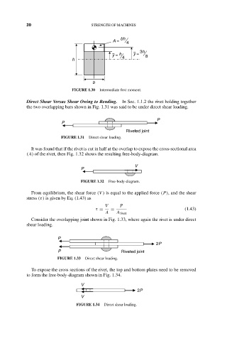
                  Direct Shear Versus Shear Owing to Bending.  In Sec. 1.1.2 the rivet holding together
                  the two overlapping bars shown in Fig. 1.31 was said to be under direct shear loading.

                                                                    P
                                P
                                                        Riveted joint
                                FIGURE 1.31  Direct shear loading.

                    It was found that if the rivet is cut in half at the overlap to expose the cross-sectional area
                  (A) of the rivet, then Fig. 1.32 shows the resulting free-body-diagram.

                                                           V
                                       P
                                       FIGURE 1.32  Free-body-diagram.

                    From equilibrium, the shear force (V ) is equal to the applied force (P), and the shear
                  stress (τ) is given by Eq. (1.43) as
                                                V     P
                                             τ =  =                            (1.43)
                                                A    A rivet
                    Consider the overlapping joint shown in Fig. 1.33, where again the rivet is under direct
                  shear loading.

                              P
                                                                    2P
                              P                       Riveted joint
                              FIGURE 1.33  Direct shear loading.
                    To expose the cross sections of the rivet, the top and bottom plates need to be removed
                  to form the free-body-diagram shown in Fig. 1.34.

                                       V
                                                            2P
                                       V
                                     FIGURE 1.34  Direct shear loading.
   43   44   45   46   47   48   49   50   51   52   53