
Page 35 - Marks Calculation for Machine Design
P. 35
P1: Shibu
January 4, 2005
12:26
Brown.cls
Brown˙C01
FUNDAMENTAL LOADINGS
t max T 17
R
0
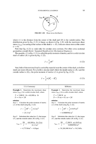
FIGURE 1.20 Shear stress distribution.
where (r) is the distance from the center of the shaft and (R) is the outside radius. The
distribution given by Eq. (1.21) is linear, as shown in Fig. 1.20, with the maximum shear
stress (τ max ) occurring at the surface of the shaft (r = R), with zero shear stress at the center
(r = 0).
Note that Eq. (1.21) is valid only for circular cross sections. For other cross-sectional
geometries consult Marks’ Standard Handbook for Mechanical Engineers.
The quantity (J) in Eq. (1.21) is called the polar moment of inertia, and for a solid circular
shaft of radius (R) is given by Eq. (1.22).
1 4
J = πR (1.22)
2
Very little of the torsional load is carried by material near the center of the shaft, so hollow
shafts are more efficient. For a hollow circular shaft where the inside radius is (R i ) and the
outside radius is (R o ), the polar moment of inertia (J) is given by Eq. (1.23).
1 4 4
J = π R − R i (1.23)
o
2
U.S. Customary SI/Metric
Example 1. Determine the maximum shear Example 1. Determine the maximum shear
stress (τ max ) for a solid circular shaft, where stress (τ max ) for a solid circular shaft, where
T = 5,000 ft · lb = 60,000 in · lb T = 7,500 N · m
D = 4in = 2R D = 10 cm = 0.1 m = 2R
solution solution
Step 1. Calculate the polar moment of inertia Step 1. Calculate the polar moment of inertia
(J) of the shaft using Eq. (1.22). (J) of the shaft using Eq. (1.22).
1 4 1 4 1 4 1 4
J = πR = π(2in) J = πR = π(0.05 m)
2 2 2 2
= 25.13 in 4 = 0.00000982 m 4
Step 2. Substitute this value for (J), the torque Step 2. Substitute this value for (J), the torque
(T ), and the outside radius (R) in Eq. (1.21). (T ), and the outside radius (R) in Eq. (1.21).
TR (60,000 in · lb)(2in) TR (7,500 N · m)(0.05 m)
τ max = = τ max = =
J 25.13 in 4 J 0.00000982 m 4
2
2
= 4,775 lb/in = 4.8 kpsi = 38,200,000 N/m = 38.2MPa