
Page 32 - Marks Calculation for Machine Design
P. 32
P1: Shibu
12:26
January 4, 2005
Brown.cls
Brown˙C01
14
STRENGTH OF MACHINES
D
t
F
B, C
A
G
g
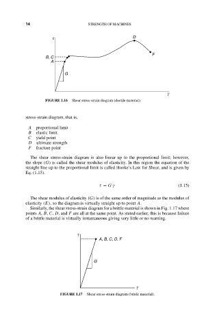
FIGURE 1.16 Shear stress-strain diagram (ductile material).
stress-strain diagram, that is,
A proportional limit
B elastic limit
C yield point
D ultimate strength
F fracture point
The shear stress-strain diagram is also linear up to the proportional limit; however,
the slope (G) is called the shear modulus of elasticity. In this region the equation of the
straight line up to the proportional limit is called Hooke’s Law for Shear, and is given by
Eq. (1.15).
τ = G γ (1.15)
The shear modulus of elasticity (G) is of the same order of magnitude as the modulus of
elasticity (E), so the diagram is virtually straight up to point A.
Similarly, the shear stress-strain diagram for a brittle material is shown in Fig. 1.17 where
points A, B, C, D, and F are all at the same point. As stated earlier, this is because failure
of a brittle material is virtually instantaneous giving very little or no warning.
t
A, B, C, D, F
G
g
FIGURE 1.17 Shear stress-strain diagram (brittle material).