
Page 22 - Marks Calculation for Machine Design
P. 22
P1: Shibu
January 4, 2005
12:26
Brown.cls
Brown˙C01
STRENGTH OF MACHINES
4
T
FIGURE 1.3 Torsion. T
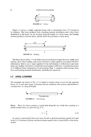
Figure 1.4 shows a simply supported beam with a concentrated force (F) located at
its midpoint. This force produces both a bending moment distribution and a shear force
distribution in the beam. At any location along the length (L) of the beam, the bending
moment produces a normal stress, and the shear force produces a shear stress.
F
L/2
A B
L
FIGURE 1.4 Bending.
The beam shown in Fig. 1.4 will deflect downward along its length; however, unlike axial
loading, direct shear loading, and torsion that have a single equation associated with their
deformation, there is not a single equation for the deformation or deflection of any beam
under any loading. Each beam configuration and loading is different. A detailed discussion
of 15 different beam configurations is presented in Chap. 2, complete with reactions, shear
force and bending moment distributions, and deflection equations.
1.2 AXIAL LOADING
The prismatic bar shown in Fig. 1.5 is loaded in tension along its axis by the opposing
forces (P) at each end. Again, a prismatic bar has a uniform cross section, and therefore a
constant area (A) along its length.
P P
Prismatic bar
FIGURE 1.5 Axial loading.
Stress. These two forces produce a tensile load along the axis of the bar, resulting in a
tensile normal stress (σ) given by Eq. (1.1).
P
σ = (1.1)
A
As stress is expressed by force over area, the unit is given in pound per square inch (psi)
in the U.S. Customary System, and in newton per square meter, or pascal (Pa), in the metric
system.