
Page 397 - Marks Calculation for Machine Design
P. 397
P1: Naresh
January 4, 2005
15:28
Brown.cls
Brown˙C09
U.S. Customary MACHINE ENERGY SI/Metric 379
Example 6. Suppose the two helical springs Example 6. Two helical springs are used in
in Example 5 are used in parallel as shown in series as shown in Fig. 9.6(a). Calculate the
Fig. 9.6(b). Calculate the equivalent spring rate equivalent spring rate (k eq ), where
(k eq ), where
k 1 = 30 lb/in k 1 = 5,400 N/m
k 2 = 60 lb/in k 2 = 10,800 N/m
solution solution
Step 1. Using Eq. (9.32), determine the equiv- Step 1. Using Eq. (9.32), determine the equiv-
alent spring rate (k eq ) as alent spring rate (k eq ) as
k eq = k 1 + k 2 k eq = k 1 + k 2
= (30 lb/in) + (60 lb/in) = (5,400 N/m) + (10,800 N/m)
= 90 lb/in = 16,200 N/m
Theequivalentspringrate(k eq )isgreaterthan Theequivalentspringrate(k eq )isgreaterthan
either of the two individual spring rates. This is either of the two individual spring rates. This is
because both springs are working together in because both springs are working together in
the system. the system.
Note that these two springs will change Note that these two springs will change
lengths at different rates, therefore the system lengths at different rates, therefore the system
may rotate to accommodate this difference. may rotate to accommodate this difference.
9.2.5 Extension Springs
Extensions springs are helical springs loaded in tension. To provide a way to connect these
springs into a mechanical system, a hook is usually fashioned from additional coils at each
end. The stress concentrations these hooks produce must be considered in the design.
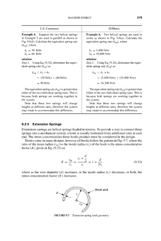
Hooks come in many designs, however all hooks follow the pattern in Fig. 9.7, where the
ratio of the mean radius (r m ) to the inside radius (r i ) of the hook is the stress-concentration
factor (K) given in Eq. (9.33) as
d
r i +
r m 2 d
K = = = 1 + (9.33)
r i r i 2r i
where as the wire diameter (d) increases, or the inside radius (r i ) decreases, or both, the
stress-concentration factor (K) increases.
Hook end
d
r i
r m
FIGURE 9.7 Extension spring hook geometry.