
Page 401 - Marks Calculation for Machine Design
P. 401
P1: Naresh
15:28
January 4, 2005
Brown˙C09
Brown.cls
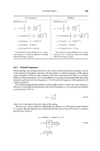
U.S. Customary MACHINE ENERGY SI/Metric 383
deflection (y cr ) as deflection (y cr ) as
1/2 1/2
2 2
λ λ
y cr = L o C 1 1 − 1 − eff y cr = L o C 1 1 − 1 − eff
C 2 C 2
1/2 1/2
2 2
(1.5) (1.5)
= (3in)(0.81) 1 − 1 − = (7.5cm)(0.81) 1 − 1 −
6.9 6.9
1/2 1/2
= (2.43 in)[1 − (1 − 0.326) ] = (7.5cm)[1 − (1 − 0.326) ]
= (2.43 in) [1 − (0.821)] = (7.5cm) [1 − (0.821)]
= (2.43 in)(0.179) = 0.44 in = (7.5cm)(0.179) = 1.3cm
Note that this critical deflection (y cr ) repre- Note that this critical deflection (y cr ) repre-
sents almost a 15 percent reduction in length sents just over a 17 percent reduction in length
before the design is unsafe. before the design is unsafe.
9.2.7 Critical Frequency
Helical springs, such as those used in the valve trains of internal combustion engines, can fail
if the frequency of loading coincides with the natural, or critical, frequency of the spring,
called resonance. Different end-conditions, like those summarized in Table 9.2, produce
different critical frequencies. To avoid problems, it is usually recommended that the spring
design be such that its critical frequency is 15 to 20 times the frequency of the applied cyclic
loading frequency.
For a helical spring positioned between flat parallel surfaces, where one of the surfaces is
driven by a sinusoidal forcing function, the critical frequency ( f cr ) in cycles per second (Hz)
is given by Eq. (9.43) as
1 k
f cr = (9.43)
2 m
where (m) is the mass of the active part of the spring.
The mass (m) can be found by multiplying the density (ρ) of the spring material times
its volume. The development of an expression for the mass of the active part of a spring is
given by Eq. (9.44) as
m = density × volume = ρ A
2
πd
= (ρ) (πDN a ) (9.44)
4
A
2 2
ρπ d DN a
=
4