
Page 399 - Marks Calculation for Machine Design
P. 399
P1: Naresh
15:28
January 4, 2005
Brown.cls
Brown˙C09
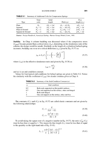
TABLE 9.1
Summary of Additional Coils for Compression Springs
Total MACHINE ENERGY Free 381
Solid
Type coils length Pitch (p) length (L o )
Plain N a (N a + 1)d (L o − d)/N a pN a + d
Squared N a + 2 (N a + 3)d (L o − 3d)/N a pN a + 3d
Plain & Ground N a + 1 (N a + 1)d L o /(N a + 1) p(N a + 1)
Squared & Ground N a + 2 (N a + 2)d (L o − 2d)/N a pN a + 2d
Source: Design Handbook, Associated Spring—Barnes Group, Bristol, Conn., 1981.
Stability. In Chap. 6 column buckling was discussed where if the compressive stress
(σ axial ) became greater than a critical stress (σ cr ), depending on the slenderness ratio of the
column, the design would be unsafe. Similarly, as the length of a cylindrical helical spring
increases, buckling can occur at a critical deflection (y cr ) given by Eq. (9.37) as
2 1/2
λ eff
y cr = L o C 1 1 − 1 − (9.37)
C 2
where (λ eff ) is the effective slenderness ratio and given by Eq. (9.38) as
αL o
λ eff = (9.38)
D
and (α) is an end-condition constant.
Values for four typical end conditions for helical springs are given in Table 9.2. Notice
the similarity with the coefficient (C ends ) for slender columns given in Chap. 6.
TABLE 9.2 Summary of the End-Condition Constant (α)
α End condition
0.5 Both ends supported on flat parallel surfaces
0.7 One end supported on flat surface, other end hinged
1 Both ends hinged
2 One end support on flat surface, other end free
The constants (C 1 ) and (C 2 ) in Eq. (9.37) are called elastic constants and are given by
the following relationships:
E
C 1 = (9.39)
2(E − G)
2
2π (E − G)
C 2 = (9.40)
2G + E
2
To avoid taking the square root of a negative number in Eq. (9.37), the ratio (λ /C 2 )
eff
must be less than or equal to 1. This means the free length (L o ) must be less than or equal
to the quantity on the right-hand side of Eq. (9.41).
1/2
π D 2(E − G)
L o ≤ (9.41)
α 2G + E