
Page 406 - Marks Calculation for Machine Design
P. 406
P1: Naresh
January 4, 2005
Brown˙C09
Brown.cls
388
U.S. Customary 15:28 APPLICATION TO MACHINES SI/Metric
Step 7. Substitute the mean shear stress (τ m ) Step 7. Substitute the mean shear stress (τ m )
from step 5 and the alternating shear stress (τ a ) from step 5 and the alternating shear stress (τ a )
from step 6, and the given endurance limit (S e ) from step 6, and the given endurance limit (S e )
and ultimate shear stress (S us ) in the Goodman and ultimate shear stress (S us ) in the Goodman
theory given in Eq. (7.34) as theory given in Eq. (7.34) as
τ a τ m 1 τ a τ m 1
+ = + =
S e S us n S e S us n
39.6 kpsi 60.5 kpsi 1 511 MPa 805 MPa 1
+ = + =
60 kpsi 140 kpsi n 420 MPa 980 MPa n
1 1
(0.660) + (0.432) = (1.217) + (0.821) =
n n
1 1
1.092 = 2.038 =
n n
1 1
n = = 0.92 (unsafe) n = 2.038 = 0.49 (very unsafe)
1.092
The fact that the factor-of-safety (n) is The fact that the factor-of-safety (n) is much
less than 1, means the spring must be re- less than 1, means the spring must be re-
designed. designed.
9.3 FLYWHEELS
Flywheels store and release the energy of rotation, called inertial energy. The primary
purpose of a flywheel is to regulate the speed of a machine. It does this through the amount
of inertia contained in the flywheel, specifically the mass moment of inertia. Flywheels are
typically mounted onto one of the axes of the machine, integral with one of the rotating
shafts. Therefore, it is the mass moment of inertia about this axis that is the most important
design parameter. As stated in the introduction to this chapter, too much inertia in the
flywheel design and the system will be sluggish and unresponsive, too little inertia and
the system will lose momentum over time. The inertia has to be just right! Determining
the right amount of inertia is the main purpose of the disussion that follows.
9.3.1 Inertial Energy of a Flywheel
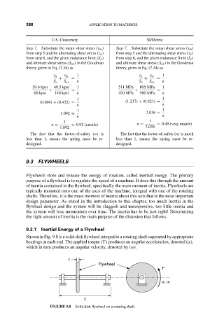
Shown in Fig. 9.8 is a solid disk flywheel integral to a rotating shaft supported by appropriate
bearings at each end. The applied torque (T ) produces an angular acceleration, denoted (α),
which in turn produces an angular velocity, denoted by (ω).
t
Flywheel
T
a, w
L
FIGURE 9.8 Solid disk flywheel on a rotating shaft.