
Page 410 - Marks Calculation for Machine Design
P. 410
P1: Naresh
January 4, 2005
15:28
Brown.cls
Brown˙C09
392
APPLICATION TO MACHINES
The torque (T ) flywheels are designed to smooth out and vary in two primary ways:
1. Varies with the rotation angle (θ)—internal combustion engine
2. Varies with the angular velocity (ω)—electric motor driven punch press
The design of flywheels for each of these variations will now be presented.
9.3.2 Internal Combustion Engine
Flywheels
The torque (T ) delivered by an internal combustion engine is a function of the rotation
angle (θ). In fact, for a four-stroke engine, power is delivered during only one of the four
◦
180 cycles. For the other three cycles, the inertia and thermodynamic processes of the
system are slowing the engine down. If the engine has only one cylinder, the variation in
torque, and therefore, the power, is greater than if the engine has multiple cylinders, say
six or eight, each delivering power at different rotation angles. However, the design of the
flywheel for this type of engine, whatever the number of cylinders, is the same.
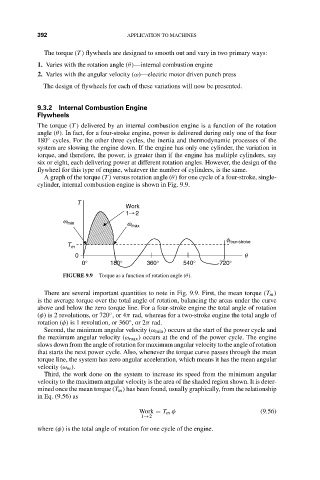
A graph of the torque (T ) versus rotation angle (θ) for one cycle of a four-stroke, single-
cylinder, internal combustion engine is shown in Fig. 9.9.
T
Work
1 2
w min w max
f four-stroke
T m
0 q
0° 180° 360° 540° 720°
FIGURE 9.9 Torque as a function of rotation angle (θ).
There are several important quantities to note in Fig. 9.9. First, the mean torque (T m )
is the average torque over the total angle of rotation, balancing the areas under the curve
above and below the zero torque line. For a four-stroke engine the total angle of rotation
(φ) is 2 revolutions, or 720 ,or4π rad, whereas for a two-stroke engine the total angle of
◦
rotation (φ) is 1 revolution, or 360 ,or2π rad.
◦
Second, the minimum angular velocity (ω min ) occurs at the start of the power cycle and
the maximum angular velocity (ω max ) occurs at the end of the power cycle. The engine
slows down from the angle of rotation for maximum angular velocity to the angle of rotation
that starts the next power cycle. Also, whenever the torque curve passes through the mean
torque line, the system has zero angular acceleration, which means it has the mean angular
velocity (ω m ).
Third, the work done on the system to increase its speed from the minimum angular
velocity to the maximum angular velocity is the area of the shaded region shown. It is deter-
mined once the mean torque (T m ) has been found, usually graphically, from the relationship
in Eq. (9.56) as
Work = T m φ (9.56)
1→2
where (φ) is the total angle of rotation for one cycle of the engine.