
Page 413 - Marks Calculation for Machine Design
P. 413
P1: Naresh
15:28
January 4, 2005
Brown.cls
Brown˙C09
U.S. Customary MACHINE ENERGY SI/Metric 395
Step 4. Substitute the mean torque (T m ) from Step 4. Substitute the mean torque (T m ) from
step 3, the angular velocity (ω m ) from step 2, step 3, the angular velocity (ω m ) from step 2,
and the given angle of rotation (φ) for one and the given angle of rotation (φ) for one
cycle and the coefficient of fluctuation (C f ) in cycle and the coefficient of fluctuation (C f ) in
Eq. (9.62) to give the required mass moment of Eq. (9.62) to give the required mass moment of
inertia for the system (I sys ) as inertia for the system (I sys ) as
T m φ (29.2ft · lb)(4π rad) T m φ (45.1N · m)(4π rad)
I sys = 2 = 2 I sys = 2 = 2
C f ω m rad C f ω m rad
(0.05) 188.5 (0.05) 188.5
s s
367 ft · lb 2 567 N · m 2
= = 0.21 (ft · lb · s ) = = 0.32 (N · m · s )
1 1
1,777 1,777
s 2 s 2
slug · ft kg · m
= 0.21 ft · · s 2 = 0.32 · m · s 2
s 2 s 2
= 0.21 slug · ft 2 = 0.32 kg · m 2
If the engine had been a two-stroke instead of If the engine had been two-stroke instead of
a four-stroke, then the amount of inertia needed four-stroke, then the amount of inertia needed
would be half the value calculated in step 4. would be half the value calculated in step 4.
9.3.3 Punch Press Flywheels
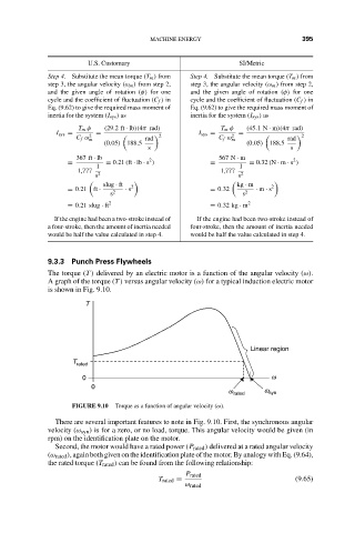
The torque (T ) delivered by an electric motor is a function of the angular velocity (ω).
A graph of the torque (T ) versus angular velocity (ω) for a typical induction electric motor
is shown in Fig. 9.10.
T
Linear region
T rated
0 w
0
w rated w syn
FIGURE 9.10 Torque as a function of angular velocity (ω).
There are several important features to note in Fig. 9.10. First, the synchronous angular
velocity (ω syn ) is for a zero, or no load, torque. This angular velocity would be given (in
rpm) on the identification plate on the motor.
Second, the motor would have a rated power (P rated ) delivered at a rated angular velocity
(ω rated ), again both given on the identification plate of the motor. By analogy with Eq. (9.64),
the rated torque (T rated ) can be found from the following relationship:
P rated
T rated = (9.65)
ω rated