
Page 414 - Marks Calculation for Machine Design
P. 414
P1: Naresh
15:28
January 4, 2005
Brown.cls
Brown˙C09
APPLICATION TO MACHINES
396
Third, this type of motor works best, mechanically and economically, in the linear region
of the curve noted in the figure. The information found on the identification plate can be
used to determine an equation of this straight line portion of the curve. Leaving out the
algebra steps, the equation of this straight line can be found to be of the form
ω syn − ω
T = T rated (9.66)
ω syn − ω rated
Therefore, for a torque (T ) there is corresponding angular velocity (ω), and vice versa.
However, usually the torque (T ) will be known from the requirements of the system to
which the electric motor is connected. A typical application is a punch press.
Punch Press. Without getting into too much detail, basically a punch press operates
cyclically to stamp out parts, or punch holes, or shapes, or both in parts. The inertial energy
of the system, most of which is contained in an appropriately designed flywheel, does the
actual punching. The electric motor that is connected to the punch press is then used to
return the flywheel to its initial punching speed before the next punching cycle begins. An
electric motor is chosen because of the properties already presented.
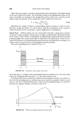
The cyclic punching process is shown in Fig. 9.11,
T
T punch
Punch Punch
One cycle
Recover
0 t
0 t 1 t 2 t 1
FIGURE 9.11 Punch press cycle—torque versus time.
where the time (t 1 ) is length of the actual punching process and time (t 2 ) is the start of the
next cycle. During the time interval (t 2 – t 1 ), the system must recover.
From the electric motor’s perspective, the motor has an angular velocity (ω 1 ) at time (t 1 ),
the end of the punching process, and must increase its speed to an angular velocity (ω 2 ) at
time (t 2 ), the start of the punching process. There are corresponding torques (T 1 ) and (T 2 )
for these two angular velocities, as shown on Fig. 9.12.
T
Linear region
T 1
T 2
0 w
0
w 1 w 2 w syn
FIGURE 9.12 Torques and angular velocities for punch press.