
Page 420 - Marks Calculation for Machine Design
P. 420
P1: Naresh
January 4, 2005
Brown˙C09
Brown.cls
402
Rim
Composite
flywheel 15:28 APPLICATION TO MACHINES Spoke
Hub
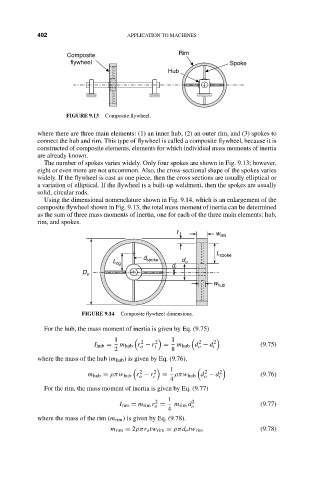
FIGURE 9.13 Composite flywheel.
where there are three main elements: (1) an inner hub, (2) an outer rim, and (3) spokes to
connect the hub and rim. This type of flywheel is called a composite flywheel, because it is
constructed of composite elements, elements for which individual mass moments of inertia
are already known.
The number of spokes varies widely. Only four spokes are shown in Fig. 9.13; however,
eight or even more are not uncommon. Also, the cross-sectional shape of the spokes varies
widely. If the flywheel is cast as one piece, then the cross sections are usually elliptical or
a variation of elliptical. If the flywheel is a built-up weldment, then the spokes are usually
solid, circular rods.
Using the dimensional nomenclature shown in Fig. 9.14, which is an enlargement of the
composite flywheel shown in Fig. 9.13, the total mass moment of inertia can be determined
as the sum of three mass moments of inertia, one for each of the three main elements: hub,
rim, and spokes.
t w rim
L
d spoke
L cg spoke d o
d i
D o
w hub
FIGURE 9.14 Composite flywheel dimensions.
For the hub, the mass moment of inertia is given by Eq. (9.75)
1 2 2 1 2 2
I hub = m hub r − r i = m hub d − d i (9.75)
o
o
2 8
where the mass of the hub (m hub ) is given by Eq. (9.76).
1
2
2
m hub = ρπw hub r − r 2 = ρπw hub d − d 2 (9.76)
o i o i
4
For the rim, the mass moment of inertia is given by Eq. (9.77)
1
2 2
I rim = m rim r = m rim d o (9.77)
o
4
where the mass of the rim (m rim ) is given by Eq. (9.78).
m rim = 2ρπr o tw rim = ρπd o tw rim (9.78)