
Page 118 - Mastering SolidWorks
P. 118
|
driVing SketcheS With Smart dimenSionS 87
NOTE if a line is not selected as the zero reference entity, the ordinate dimension feature defaults to
a horizontal ordinate.
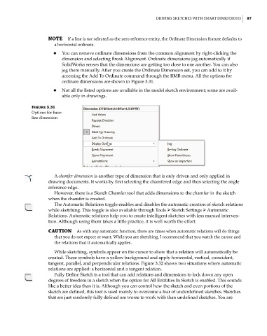
◆ You can remove ordinate dimensions from the common alignment by right-clicking the
dimension and selecting Break Alignment. Ordinate dimensions jog automatically if
SolidWorks senses that the dimensions are getting too close to one another. You can also
jog them manually. After you create the Ordinate Dimension set, you can add to it by
accessing the Add To Ordinate command through the RMB menu. All the options for
ordinate dimensions are shown in Figure 3.31.
◆ Not all the listed options are available in the model sketch environment; some are avail-
able only in drawings.
Figure 3.31
options for base-
line dimension
A chamfer dimension is another type of dimension that is only driven and only applied in
drawing documents. It works by first selecting the chamfered edge and then selecting the angle
reference edge.
However, there is a Sketch Chamfer tool that adds dimensions to the chamfer in the sketch
when the chamfer is created.
The Automatic Relations toggle enables and disables the automatic creation of sketch relations
while sketching. This toggle is also available through Tools ➢ Sketch Settings ➢ Automatic
Relations. Automatic relations help you to create intelligent sketches with less manual interven-
tion. Although using them takes a little practice, it is well worth the effort.
CAUTION as with any automatic function, there are times when automatic relations will do things
that you do not expect or want. While you are sketching, i recommend that you watch the cursor and
the relations that it automatically applies.
While sketching, symbols appear on the cursor to show that a relation will automatically be
created. These symbols have a yellow background and apply horizontal, vertical, coincident,
tangent, parallel, and perpendicular relations. Figure 3.32 shows two situations where automatic
relations are applied: a horizontal and a tangent relation.
Fully Define Sketch is a tool that can add relations and dimensions to lock down any open
degrees of freedom in a sketch when the option for All Entitities In Sketch is enabled. This sounds
like a better idea than it is. Although you can control how the sketch and even portions of the
sketch are defined, this tool is used mainly to overcome a fear of underdefined sketches. Sketches
that are just randomly fully defined are worse to work with than undefined sketches. You are