
Page 121 - Mastering SolidWorks
P. 121
|
90 CHAPTER 3 Working With SketcheS and reference geometry
When the cursor displays a small sketch-relation symbol with a yellow background, an
automatic relation will be applied. If the relation symbol has a white background, the relation is
inferenced, but not applied, as an actual sketch relation. The symbols with the blue background
are relations that have been applied to existing sketch entities. Be aware that differences in
versions and differences in color schemes can cause these colors to be different on your system.
(The color may be green in SolidWorks 2008 or later. The symbols look the same, regardless of
background color.)
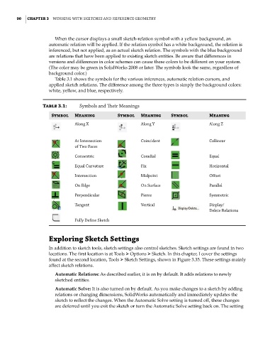
Table 3.1 shows the symbols for the various inferences, automatic relation cursors, and
applied sketch relations. The difference among the three types is simply the background colors:
white, yellow, and blue, respectively.
Table 3.1: Symbols and Their meanings
Symbol Meaning Symbol Meaning Symbol Meaning
along X along y along Z
at intersection coincident collinear
of two faces
concentric coradial equal
equal curvature fix horizontal
intersection midpoint offset
on edge on Surface Parallel
Perpendicular Pierce Symmetric
tangent Vertical display/
delete relations
fully define Sketch
Exploring Sketch Settings
In addition to sketch tools, sketch settings also control sketches. Sketch settings are found in two
locations. The first location is at Tools ➢ Options ➢ Sketch. In this chapter, I cover the settings
found at the second location, Tools ➢ Sketch Settings, shown in Figure 3.35. These settings mainly
affect sketch relations.
Automatic Relations: As described earlier, it is on by default. It adds relations to newly
sketched entities.
Automatic Solve: It is also turned on by default. As you make changes to a sketch by adding
relations or changing dimensions, SolidWorks automatically and immediately updates the
sketch to reflect the changes. When the Automatic Solve setting is turned off, these changes
are deferred until you exit the sketch or turn the Automatic Solve setting back on. The setting