
Page 125 - Mastering SolidWorks
P. 125
|
94 CHAPTER 3 Working With SketcheS and reference geometry
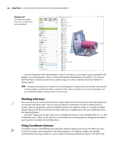
Figure 3.37
creating a new plane
from a set of selections
and constraints
A newer function of the Plane feature is that it will allow you to make a plane parallel to the
display at a selected point. This is a somewhat hidden functionality. To enable it, you have to
start the Plane command; and select a point, origin, or vertex; and then click the Parallel To
Screen option.
TIP Because most planes are created from an existing plane or planar face, you should customize the
context toolbar to include the Plane command. then, when you select a face from the graphic area,
you will find the Plane command next to your cursor.
Working with Axes
You can use axes to create pivot points in a part where you do not have any hole-type geometry
for mating with other parts. You can also use them as a direction of pull for plastic parts or
molds. Axes are frequently used to establish direction for rotation, draft, or a number of other
things. Figure 3.38 shows that the first three features in a plastic part are axes established from
the standard planes.
Consider using axes set up in this way as standard features in your template files (X-, Y-, and
Z-direction axes). They can be effective in assemblies for moving parts in orthogonal directions
and in parts for pattern or draft directions.
Using Coordinate Systems
Coordinate systems in SolidWorks are primarily used for import and export, but they also can
be used for mates, mass properties, and other purposes. Coordinate systems are usually
positioned by selecting a point or a set of edges to determine direction. Figure 3.39 shows the