
Page 161 - Mastering SolidWorks
P. 161
|
130 CHAPTER 4 Creating Simple partS and drawingS
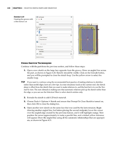
Figure 4.19
Creating the groove with
a thin feature cut
Using Sketch Techniques
Continue with the part from the previous section, and follow these steps:
1. Open a new sketch on the large face opposite from the groove. Draw an angled line across
the part, as shown in Figure 4.20. Sketch1 should be visible. Click on the Extrude button,
and you will be prompted to close the sketch loop. Use the yellow arrow to select the
smaller loop.
TIP if you want to continue using the recommended best practice of making relations to sketches
rather than model edges, here are a few tips. in some situations (such as the current one), the sketch
plane is offset from the sketch that you want to make relations to, and the best bet is to use the nor-
mal to view. the next obstacle is making sure that automatic relations pick up the sketch rather than
the edge, so you can use the Selection Filter to select sketch entities only.
2. Extrude the sketch to add 0.25-inch material.
3. Choose Tools ➢ Options ➢ Sketch and ensure that Prompt To Close Sketch is turned on;
then click OK to close the dialog box.
4. Open another new sketch on the same face that was used by the last extrusion. Begin
drawing another angled line, but before placing the second endpoint, hover the cursor
over the angled edge created by the previous feature, and it will highlight orange. Now
position the cursor approximately to make a parallel line, and a dotted yellow inference
will appear. Draw the angled line using all the automatic relationships that are appropri-
ate, as shown in Figure 4.21.