
Page 160 - Mastering SolidWorks
P. 160
|
Creating a Simple drawing 129
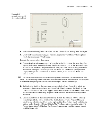
Figure 4.18
a simple drawing with
views and a title block
3. Sketch a center rectangle that is 6-inches tall and 4-inches wide, starting from the origin.
4. Create an Extrude feature, using the Direction 1 option for Mid Plane, with a depth of
1 inch. Before you accept the Extrude.
To create the groove, follow these steps:
1. Open a sketch on a face of the part that’s parallel to the Front plane. To create the offset,
expand the Extrude feature by clicking the plus icon (+) next to it in the FeatureManager
so you can see the sketch. Regardless of how it displays here, this sketch appears before
the extrude in the part history. Right-click the sketch and select Show (or expand the
DisplayManager and click the icon in the first column, in the row of the sketch you
want to show).
TIP You can view individual sketches and reference geometry entities such as planes from the rmB
menu. the global settings for the visibility of these items are found in the View menu. You can access
these items faster by using the View toolbar or by linking the commands to hotkeys.
2. Right-click the sketch in the graphics window, and click Select Chain. This selects any
nonconstruction, end-to-end sketch entities. Click Offset Entities on the Sketch toolbar.
Offset to the inside by .400 inches. Apply .500-inch sketch fillets to each of the corners. Exit
out of the Fillet command using the green check when the fillets have been applied to
the sketch.
3. Click Extruded Cut on the Feature toolbar. By default, the extruded cut will cut away
everything inside the closed profile of the sketch. Look down the PropertyManager
window, and select the check box on the top bar of the Thin Feature panel. Make the cut
settings under Direction 1 Blind, .100 inch. The Thin Feature type should be set to Mid
Plane with a width of .400 inches. The PropertyManager and graphics window should
look like Figure 4.19.