
Page 155 - Mastering SolidWorks
P. 155
|
124 CHAPTER 4 Creating Simple partS and drawingS
The next modeling step is to create a groove on the back of the part. How is this feature going
to be made? You can use several techniques to create this geometry. List as many techniques as
you can think of, whether or not you know how to use them.
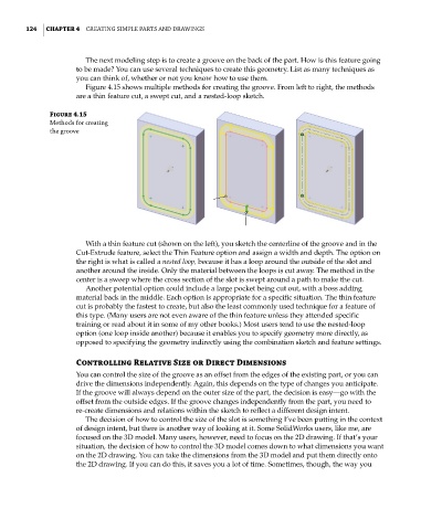
Figure 4.15 shows multiple methods for creating the groove. From left to right, the methods
are a thin feature cut, a swept cut, and a nested-loop sketch.
Figure 4.15
methods for creating
the groove
With a thin feature cut (shown on the left), you sketch the centerline of the groove and in the
Cut-Extrude feature, select the Thin Feature option and assign a width and depth. The option on
the right is what is called a nested loop, because it has a loop around the outside of the slot and
another around the inside. Only the material between the loops is cut away. The method in the
center is a sweep where the cross section of the slot is swept around a path to make the cut.
Another potential option could include a large pocket being cut out, with a boss adding
material back in the middle. Each option is appropriate for a specific situation. The thin feature
cut is probably the fastest to create, but also the least commonly used technique for a feature of
this type. (Many users are not even aware of the thin feature unless they attended specific
training or read about it in some of my other books.) Most users tend to use the nested-loop
option (one loop inside another) because it enables you to specify geometry more directly, as
opposed to specifying the geometry indirectly using the combination sketch and feature settings.
Controlling Relative Size or Direct Dimensions
You can control the size of the groove as an offset from the edges of the existing part, or you can
drive the dimensions independently. Again, this depends on the type of changes you anticipate.
If the groove will always depend on the outer size of the part, the decision is easy—go with the
offset from the outside edges. If the groove changes independently from the part, you need to
re-create dimensions and relations within the sketch to reflect a different design intent.
The decision of how to control the size of the slot is something I’ve been putting in the context
of design intent, but there is another way of looking at it. Some SolidWorks users, like me, are
focused on the 3D model. Many users, however, need to focus on the 2D drawing. If that’s your
situation, the decision of how to control the 3D model comes down to what dimensions you want
on the 2D drawing. You can take the dimensions from the 3D model and put them directly onto
the 2D drawing. If you can do this, it saves you a lot of time. Sometimes, though, the way you