
Page 154 - Mastering SolidWorks
P. 154
|
Creating a Simple part 123
when used in conjunction with the direct editing type of tools such as Move Face. Instant 3D
mimics some of the direct edit type of functionality found in applications such as Solid Edge,
SketchUp, and SpaceClaim.
NOTE when combined with the sketch setting Override dims On drag (found at tools ➢ Options ➢
Sketch ➢ Override dimensions On drag/move), instant 3d can be a powerful concepting tool, even
on fully dimensioned sketches.
Instant 3D also offers a tool called Live Section, which enables you to section a part with a
plane or drag the edges of the section regardless of the features to which the edges belong. To
activate Live Section, right-click a plane that intersects the part and select Live Section Plane.
Live Section is shown in Figure 4.13.
Chapter 37, “Using Imported Geometry,” discusses the direct edit theme in more detail and
revisits the Instant 3D manipulators in that light.
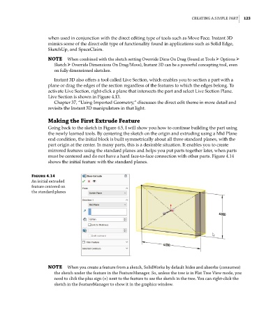
Making the First Extrude Feature
Going back to the sketch in Figure 4.5, I will show you how to continue building the part using
the newly learned tools. By centering the sketch on the origin and extruding using a Mid Plane
end condition, the initial block is built symmetrically about all three standard planes, with the
part origin at the center. In many parts, this is a desirable situation. It enables you to create
mirrored features using the standard planes and helps you put parts together later, when parts
must be centered and do not have a hard face-to-face connection with other parts. Figure 4.14
shows the initial feature with the standard planes.
Figure 4.14
an initial extruded
feature centered on
the standard planes
NOTE when you create a feature from a sketch, Solidworks by default hides and absorbs (consumes)
the sketch under the feature in the Featuremanager. So, unless the tree is in Flat tree View mode, you
need to click the plus sign (+) next to the feature to see the sketch in the tree. You can right-click the
sketch in the Featuremanager to show it in the graphics window.