
Page 151 - Mastering SolidWorks
P. 151
|
120 CHAPTER 4 Creating Simple partS and drawingS
Through All: The Through All end condition is available only when solid geometry already
exists in the part. When used for an extruded boss (which adds material), it extrudes to the
distance of the farthest point of the solid model in a direction perpendicular to the sketch
plane. When used for a cut, it simply cuts through everything.
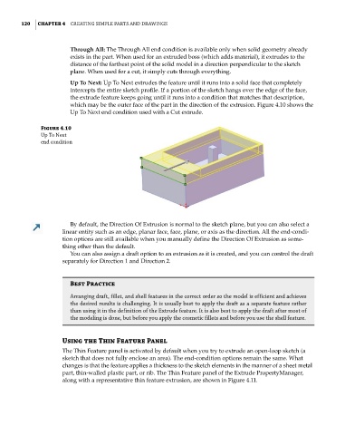
Up To Next: Up To Next extrudes the feature until it runs into a solid face that completely
intercepts the entire sketch profile. If a portion of the sketch hangs over the edge of the face,
the extrude feature keeps going until it runs into a condition that matches that description,
which may be the outer face of the part in the direction of the extrusion. Figure 4.10 shows the
Up To Next end condition used with a Cut extrude.
Figure 4.10
Up to next
end condition
By default, the Direction Of Extrusion is normal to the sketch plane, but you can also select a
linear entity such as an edge, planar face, face, plane, or axis as the direction. All the end-condi-
tion options are still available when you manually define the Direction Of Extrusion as some-
thing other than the default.
You can also assign a draft option to an extrusion as it is created, and you can control the draft
separately for Direction 1 and Direction 2.
Best Practice
arranging draft, fillet, and shell features in the correct order so the model is efficient and achieves
the desired results is challenging. it is usually best to apply the draft as a separate feature rather
than using it in the definition of the extrude feature. it is also best to apply the draft after most of
the modeling is done, but before you apply the cosmetic fillets and before you use the shell feature.
Using the Thin Feature Panel
The Thin Feature panel is activated by default when you try to extrude an open-loop sketch (a
sketch that does not fully enclose an area). The end-condition options remain the same. What
changes is that the feature applies a thickness to the sketch elements in the manner of a sheet metal
part, thin-walled plastic part, or rib. The Thin Feature panel of the Extrude PropertyManager,
along with a representative thin feature extrusion, are shown in Figure 4.11.