
Page 146 - Mastering SolidWorks
P. 146
|
Creating a Simple part 115
Notice where the part is placed in relation to the origin. Different people might do this
differently, and the same person might even do it differently depending on the function of the
part. In this case, the origin is aligned with the center of the round shape and at the bottom of
the flat face. The placement of the origin suggests that this part sits on the flat face of another
part and may hold a cylindrical face of another part.
If you open the part from www.wiley.com/go/mastersolid, you will notice that the origin is
also placed in the middle of the extrusion depth. This suggests that the part is symmetrical from
front to back.
If you are new to 3D modeling, this might be too much to take in all at once, but you should
try to keep the ideas presented here in mind as you work through your first several parts and
when you examine SolidWorks parts made by more-experienced users.
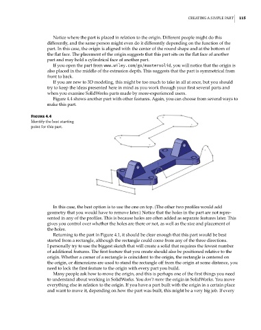
Figure 4.4 shows another part with other features. Again, you can choose from several ways to
make this part.
Figure 4.4
identify the best starting
point for this part.
In this case, the best option is to use the one on top. (The other two profiles would add
geometry that you would have to remove later.) Notice that the holes in the part are not repre-
sented in any of the profiles. This is because holes are often added as separate features later. This
gives you control over whether the holes are there or not, as well as the size and placement of
the holes.
Returning to the part in Figure 4.1, it should be clear enough that this part would be best
started from a rectangle, although the rectangle could come from any of the three directions.
I personally try to use the biggest sketch that will create a solid that requires the fewest number
of additional features. The first feature that you create should also be positioned relative to the
origin. Whether a corner of a rectangle is coincident to the origin, the rectangle is centered on
the origin, or dimensions are used to stand the rectangle off from the origin at some distance, you
need to lock the first feature to the origin with every part you build.
Many people ask how to move the origin, and this is perhaps one of the first things you need
to understand about working in SolidWorks. You don’t move the origin in SolidWorks. You move
everything else in relation to the origin. If you have a part built with the origin in a certain place
and want to move it, depending on how the part was built, this might be a very big job. If every