
Page 147 - Mastering SolidWorks
P. 147
|
116 CHAPTER 4 Creating Simple partS and drawingS
feature was created dimensioned from the origin, you will have to move every feature. If features
were created dimensioned from an edge of the first feature, you only need to move the first
feature. It is also possible to move the entire body, but that is a more complex operation that will
be addressed later.
When working with a simple part, the entire part can sometimes be described as rectangular or
cylindrical. In cases like these, it is easy to know where to start: You simply draw a rectangle or a
circle, respectively. On complex parts, it may not be obvious where to start, and the overall part
cannot be said to have any simple shape. In cases like these, it may be best to select the (or a)
prominent feature, mounting location, functional shape, or focus of the mechanism. For example,
if you were to design an automobile, what would you designate as the 0,0,0 origin? The ground
might be a reasonable location, as would the plane of the centers of the wheels. The end of the
crankshaft in the engine is often used as the assembly origin in automotive modeling. As long as
everyone working on the project agrees, many different reference points could work. With that in
mind, it seems logical to start the rectangular part by sketching a rectangle. Select the Top plane,
and sketch a centerpoint rectangle centered on the part origin.
Building in Symmetry
Your next decision is about part symmetry. The part in Figure 4.1 is not completely symmetrical.
Modeling a quarter of it and mirroring the entire model twice is not the most effective technique.
Instead, you should build the complete part around the origin and mirror individual features as
appropriate. To start this type of symmetry, you need to sketch a rectangle centered on the origin.
Again, to some extent, this is personal judgment.
Sketch a center rectangle where the first point, the centerpoint, is created at the origin. Drag or
click the second point (one of the corners) to an approximate size. This creates symmetry in both
directions. You can use additional construction geometry and sketch relations to make the
rectangle symmetrical side-to-side only.
TIP to make a rectangle work like a square, use an equal sketch relation on two adjacent sides. this
requires only a single dimension to drive the size of the square.
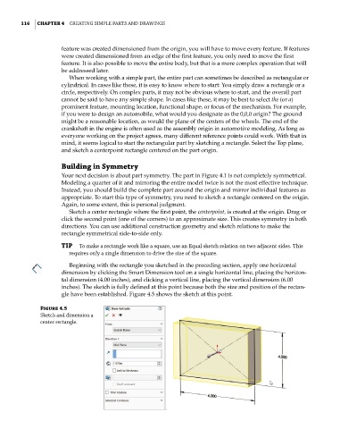
Beginning with the rectangle you sketched in the preceding section, apply one horizontal
dimension by clicking the Smart Dimension tool on a single horizontal line, placing the horizon-
tal dimension (4.00 inches), and clicking a vertical line, placing the vertical dimension (6.00
inches). The sketch is fully defined at this point because both the size and position of the rectan-
gle have been established. Figure 4.5 shows the sketch at this point.
Figure 4.5
Sketch and dimension a
center rectangle.