
Page 144 - Mastering SolidWorks
P. 144
|
Creating a Simple part 113
◆ Use a method other than history-based design. This would require a different software
package, such as Solid Edge. SolidWorks, in fact, cannot do what is known as “direct
modeling,” although the company will tell you otherwise.
I discuss this issue again in Chapter 12, “Editing, Evaluating, and Troubleshooting.”
Creating a Simple Part
Chapter 2, “Navigating the SolidWorks Interface,” introduced the tools and features you will use
to create simple parts, and this chapter teaches you how to string the simple features together
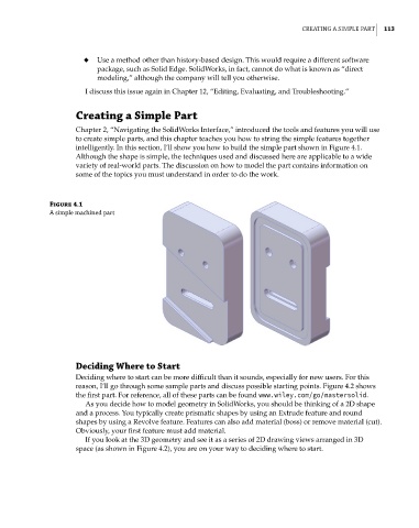
intelligently. In this section, I’ll show you how to build the simple part shown in Figure 4.1.
Although the shape is simple, the techniques used and discussed here are applicable to a wide
variety of real-world parts. The discussion on how to model the part contains information on
some of the topics you must understand in order to do the work.
Figure 4.1
a simple machined part
Deciding Where to Start
Deciding where to start can be more difficult than it sounds, especially for new users. For this
reason, I’ll go through some sample parts and discuss possible starting points. Figure 4.2 shows
the first part. For reference, all of these parts can be found www.wiley.com/go/mastersolid.
As you decide how to model geometry in SolidWorks, you should be thinking of a 2D shape
and a process. You typically create prismatic shapes by using an Extrude feature and round
shapes by using a Revolve feature. Features can also add material (boss) or remove material (cut).
Obviously, your first feature must add material.
If you look at the 3D geometry and see it as a series of 2D drawing views arranged in 3D
space (as shown in Figure 4.2), you are on your way to deciding where to start.