
Page 139 - Mastering SolidWorks
P. 139
|
108 CHAPTER 3 Working With SketcheS and reference geometry
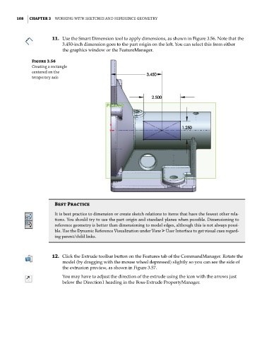
11. Use the Smart Dimension tool to apply dimensions, as shown in Figure 3.56. Note that the
3.450-inch dimension goes to the part origin on the left. You can select this from either
the graphics window or the FeatureManager.
Figure 3.56
creating a rectangle
centered on the
temporary axis
Best Practice
it is best practice to dimension or create sketch relations to items that have the fewest other rela-
tions. you should try to use the part origin and standard planes when possible. dimensioning to
reference geometry is better than dimensioning to model edges, although this is not always possi-
ble. Use the dynamic reference Visualization under View ➢ User interface to get visual cues regard-
ing parent/child links.
12. Click the Extrude toolbar button on the Features tab of the CommandManager. Rotate the
model (by dragging with the mouse wheel depressed) slightly so you can see the side of
the extrusion preview, as shown in Figure 3.57.
You may have to adjust the direction of the extrude using the icon with the arrows just
below the Direction1 heading in the Boss-Extrude PropertyManager.