
Page 136 - Mastering SolidWorks
P. 136
|
tUtoriaL: creating reference geometry 105
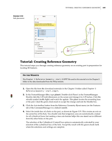
Figure 3.52
Belt placement
Tutorial: Creating Reference Geometry
This tutorial steps you through creating reference geometry on an existing part in preparation for
locating 3D features.
On the Website
the Chapter 3 Reference Geometry- start.SLDPRT file used in this tutorial is in the chapter 3
folder in the data downloaded from the Wiley website.
1. Open the file from the download materials in the Chapter 3 folder called Chapter 3
Reference Geometry - start.sldprt.
2. In the FeatureManager filter, type plane1. Double-click Plane1 in the FeatureManager.
Double-click the 3.25-inch dimension on the screen and change it to 3.35 inches. Click the
rebuild symbol (traffic light) and watch the update. This plane locates the mounting base
of the part. Click the green check mark to accept the change and exit the Modify box.
3. Click the Axis toolbar button from the Reference Geometry flyout menu (on the Features
tab of the CommandManager in a default install).
4. Select the inside face of a hole on the part, as shown in Figure 3.53. This creates an axis on
the centerline of the hole. You should note that temporary axes are automatically created
for all cylindrical faces, but making a true axis feature helps this one stand out as different
from the other holes on the part.
The selection of the Cylindrical/Conical Face option is automatically activated by your
selection of the cylindrical face of the hole. Accept the result with the green check mark
when the selections and settings are complete.