
Page 138 - Mastering SolidWorks
P. 138
|
tUtoriaL: creating reference geometry 107
Click the green check mark to accept the result.
7. Open a new sketch on the new plane.
8. Click the View ➢ Hide/Show menu and activate the Temporary Axes option. You should
now see blue axes (without names) appear along the centerlines of every conical or
cylindrical face on the model (except for faces created by fillet or chamfer features).
NOTE the View orientation toolbar appears when you press the spacebar; it is also available from
the heads Up View toolbar. you can also use ctrl+spacebar to access the View Selector cube. if the
view is already normal to the selected plane and you double-click normal to, the view switches to 180
degrees opposite. the setting to auto-rotate the view normal to the sketch plane when a new sketch is
opened is located at tools ➢ options ➢ Sketch.
9. Select the sketch plane either from the graphics window or the FeatureManager. Press the
spacebar on the keyboard and double-click Normal To. You can click the pushpin to keep
this box available. There are other ways to access this command, but this is the method
that works regardless of your interface setup.
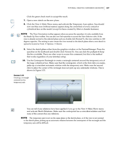
10. Use the Centerpoint Rectangle to create a rectangle centered around the temporary axis of
the large cylindrical face. Make sure that the centerpoint, which is the first click you make,
picks up a coincident automatic relation with the temporary axis. Make sure the second
click to place the corner of the rectangle does not pick up any automatic relations. This is
shown in Figure 3.55.
Figure 3.55
creating a rectangle
centered on the
temporary axis
You can tell if any relations have been applied if you go to the View ➢ Hide/Show menu
and activate Sketch Relations. Make sure the centerpoint has a coincident relation and that
none of the corners has any relations.
NOTE the temporary axis is not on the same plane as the sketch plane, so if the view is not normal
to the sketch plane, picking up an automatic relation between the centerpoint of the rectangle and the
temporary axis will be difficult.